Hercules-EBX CPU User Manual V1.02
Page 14
4.3 PS/2 Connector – J6
An 8-pin connector is provided for PS/2 Mouse and keyboard. This connector mates with
Diamond Systems’ cable no. 698022, which terminates the cable to two PS/2 Female connectors
.
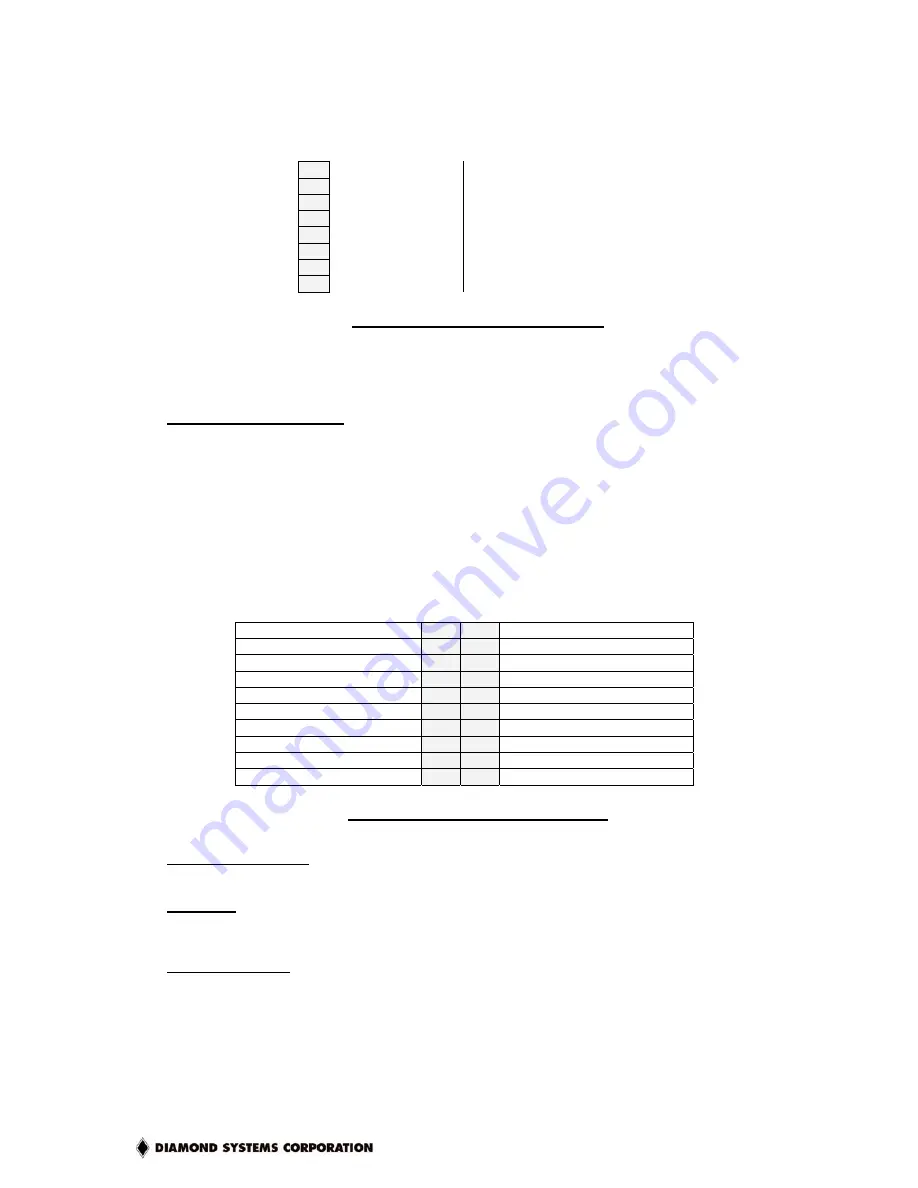
The connections are:
1
+5V In
Keyboard PS/2 : pin 4
2
Keyboard Data
Keyboard PS/2 : pin 1
3
Keyboard Clock
Keyboard PS/2 : pin 5
4
Ground
Keyboard PS/2 : pin 3
5
+5V In
Mouse PS/2 : pin 4
6
Mouse Data
Mouse PS/2 : pin 1
7
Mouse Clock
Mouse PS/2 : pin 5
8
Ground
Mouse PS/2 : pin 3
Table 3: J6 - PS/2 Connector Pinout
Note: 2 and 6 on the Mini-Din-6 PS/2 connectors are unused.
Connector Part Numbers
J6 plug on CPU board:
Digikey 640456-8
Mating Connector for J6 (Cable-mount socket):
Molex 22-01-3087
PS/2
Connector:
CUI
MD60SP
4.4 Utility Connector – J7
A 20-pin connector provides access to the standard button/LED connections:
Ground
1
2
Reset Key
Ground
3
4
Power Button
Network : Activity LED
5
6
+3.3V Standby
Network : 100MBit link
7
8
+3.3V Standby
+5V In
9
10
IDE LED
Power LED
11
12
External Battery
Watch Dog Timer - Input
13
14
Ground
SPEAKER
15
16
Watch Dog Timer - Output
+5V In
17
18
IRTX (IR Transmit)
IRRX (IR Receive)
19
20
Ground
Table 4: J7 - Utility Connector Pinout
Notes on J7 Signals
Reset Key
Connection between this pin and Ground will generate a Reset
condition. The board will be in a reset state (with non-standby power
rails disabled) until “Reset Key” is removed from ground.
ATX Power Button
This should be tied to ground whenever the “Power Button” is to be
depressed. The “Power Button” has different functionality, depending
on the current system mode (as well as what software is currently in
operation). In general,
•
If the board is powered down, then toggling (i.e., tie to ground
briefly, then release) this button turns the system on, causing all
non-standby voltages to become active. NOTE: depending on the
default configuration, the system will usually power-up immediately
as power is applied.


