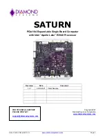
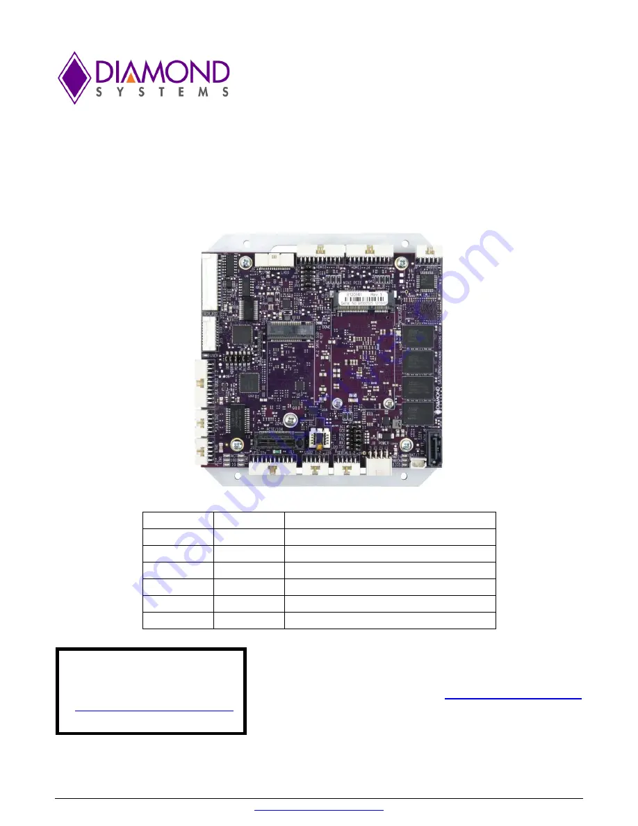
background image

Saturn User Manual V1.01 

www.diamondsystems.com


Page 1 


SATURN


PCIe/104 Expandable Single Board Computer 

with 

Intel “Apollo Lake” E3940 Processor


FOR TECHNICAL SUPPORT


Copyright 2021


PLEASE CONTACT:


Diamond Systems Corporation


www.diamondsystems.com


support@diamondsystems.com


Revision 

Date 

Comment


1.01 

09/13/2021 

Initial Release 


Summary of Contents for SATURN SAT-E3940-4GA

Page 1: ...CIe 104 Expandable Single Board Computer with Intel Apollo Lake E3940 Processor FOR TECHNICAL SUPPORT Copyright 2021 PLEASE CONTACT Diamond Systems Corporation www diamondsystems com support diamondsy...

Page 2: ...ower Supply 13 3 3 Rugged Design 14 4 Board Mechanical Drawing 15 5 Connector and Jumper Locations 16 6 I O Connectors 19 6 1 Connector Pin out and Signal Description 19 6 1 1 Power In J8 19 6 1 2 Ext...

Page 3: ...Quiet Quick Boot Splash Screen 34 9 8 Serial Port Configuration 34 10 Getting Started 35 10 1 Quick Setup 35 10 2 Boot Device Options 35 10 3 Installing OS and Booting 36 11 Video Features 37 12 Seria...

Page 4: ...to avoid possible shorting from this type of damage However these design rules are not sufficient to prevent damage in all situations A third cause of failure is when a metal screwdriver tip slips or...

Page 5: ...ptable range of voltages connected to digital I O signals is 0 5V and they can withstand about 0 5V beyond that 0 5 to 5 5V before being damaged However logic signals at 12V and even 24V are common an...

Page 6: ...A x5 3940 1 80 GHz 4 8GB ECC Analog Digital I O SAT E3940 8GED x5 3940 1 80 GHz 4 8GB ECC Digital I O 2 2 Features Processor Apollo lake x5 3940 Quad Core 1 6GHz 9 5W TDP Apollo lake x5 3930 Dual Core...

Page 7: ...k PCIe 104 with 4 PCIe x1 2 USB2 0 2 3 Operating System Support Windows 10 64bit Linux 64bit Driver packages and or BSPs available for each OS 2 4 Mechanical Electrical Environmental Form factor 4 5 W...

Page 8: ...Saturn User Manual V1 www diamondsystems com Page 8 3 FUNCTIONAL OVERVIEW 3 1 Block Diagram Block Diagram...

Page 9: ...ivity and Speed The LEDs are located along the board edge near the Ethernet connector The GbE ports use dual row 2x5 2mm pitch latching connectors The connector does not provide access to the LED sign...

Page 10: ...support RS 232 422 485 protocols using Exar SP336 multiprotocol transceivers Protocol selection are controlled by FPGA gpio and configurable via application software TX RX 121 ohm line termination re...

Page 11: ...lly TCG TPM 1 2 2 0 standard compliant module with an SPI interface TPM can be used as a root of trust for platform integrity remote attestation and cryptographic services 3 2 13 PCIe link routing Apo...

Page 12: ...1 each for Link Activity and Speed per port DONE FPGA is configured successfully USER Blue User LED controlled by processor FPGA 3 2 17 BIOS Features The BIOS provides the following key features Boot...

Page 13: ...Maximum allowable reflected ripple measured at the voltage input connector is 50mV p p All required supply voltages for the board are derived from the 5V input These power supplies are sized to suppo...

Page 14: ...cker PCB increases rigidity and improves reliability of fine pitch and high ball count BGA solder joints All I O connectors are latching for increased ruggedness A bottom side heat spreader provides m...

Page 15: ...Saturn User Manual V1 www diamondsystems com Page 15 4 BOARD MECHANICAL DRAWING Dimensions are in inches mm Connector dimensions indicate the center of the pad for pin 1 Mechanical Drawing...

Page 16: ...Saturn User Manual V1 01 www diamondsystems com Page 16 5 CONNECTOR AND JUMPER LOCATIONS Board layout Top...

Page 17: ...Saturn User Manual V1 www diamondsystems com Page 17 Board layout Bottom...

Page 18: ...Standard Middle LED GBE0 Link100 J7 External Battery Bottom LED GBE0 Link1000 J8 Power In LED Block 1 ETH2 J9 Serial Ports 1 2 Top LED GBE1 ACT J10 USB2 Port x2 Middle LED GBE1 Link100 J11 LPC Bus Bot...

Page 19: ...nal battery via connector J7 for longer battery life or long term maintainability 1 VBAT 2 Ground VBAT 3 0V Connector used is 22 05 7025 right angle type friction lock pin header Mating cable DSC 6980...

Page 20: ...section for pinouts 6 1 4 USB 2 0 Ports J10 The USB2 0 connector provides access to two USB 2 0 ports The pinouts are as below Key A01 B01 Shield USB0 Pwr A02 B02 USB1 Pwr USB0 Data A03 B03 USB1 Data...

Page 21: ...nt If DC current exceeds this value the polyswitch will heat up and create a high resistance to limit current flow The current is reduced to the level required to maintain the resistance maintaining a...

Page 22: ...l power is jumper selectable for 3 3V default or 5V VDD 5V 3 3V 1 2 VDD 5V 3 3V VDD 5V 3 3V 3 4 VDD 5V 3 3V CLK Odd 5 6 CLK Even CLK Odd 7 8 CLK Even Ground 9 10 Ground D0 Odd 11 12 D0 Even D0 Odd 13...

Page 23: ...ectable 2 Power same as pin 1 3 Ground 4 Ground 5 Enable GPIO output 0 off open circuit on 6 Brightness 0 5VDC variable 0V max 5V min Connector Type 1x6 1 25mm pitch SMD RA header of Molex 053261 0671...

Page 24: ...V 5V system voltage rail through a polyswitch resettable fuse The fuse is rated for 100mA maximum sustained current Ain 0 1 2 Ain 8 Ain 1 3 4 Ain 9 Ain 2 5 6 Ain 10 Ain 3 7 8 Ain 11 Ain 4 9 10 Ain 12...

Page 25: ...10 PCIe 1 Clk 11 12 PCIe 1 Clk 13 14 Gnd 15 16 KEY 17 18 Gnd 19 20 Disable Gnd 21 22 PCIe Reset PCIe 1 RX 23 24 3 3V PCIe 1 RX 25 26 Gnd Gnd 27 28 1 5V Gnd 29 30 SMB Clk PCIe 1 TX 31 32 SMB Data PCIe...

Page 26: ...4 3 3V 5 6 7 8 9 10 11 12 13 14 15 16 17 18 19 20 Gnd 21 22 23 24 25 26 Gnd 27 28 29 30 31 32 Gnd 33 34 35 36 37 38 DEVSLP Gnd 39 40 SATA_RX 41 42 SATA_RX 43 44 Gnd 45 46 SATA_TX 47 48 SATA_TX 49 50...

Page 27: ...ing Cable Board to board connection only USB OC 1 5 V T A B 2 PCIe Reset 3 3V 3 4 3 3V USB_1 5 6 USB_0 USB_1 7 8 USB_0 Ground 9 10 Ground PCIe1 Tx 11 12 PCIe0 Tx PCIe1 Tx 13 14 PCIe0 Tx Ground 15 16 G...

Page 28: ...Pos 2mm Pitch T H Right Angle Latching 10073599 010LF 6980603 Ethernet Amphenol 98414 F06 10ULF 10 Pos 2mm Pitch T H Vertical Angle Latching 10073599 010LF 6980604 HDMI Amphenol 98464 G61 20ULF 20 Po...

Page 29: ...nector 1 6980512 Power in J8 2 6980524 External Battery J7 J93 6980601 Serial Port J9 4 6980602 USB2 0 J10 5 6980603 USB3 0 J15 J16 6 6980604 Ethernet J13 J14 7 6980605 HDMI J3 J4 8 6980608 Audio J5 9...

Page 30: ...TION Following drawing shows only the connectors and jumper blocks on the board The default jumper positions are shown in blue Default Jumper locations Jumper Description JP1 LVDS LCD VCC and Backligh...

Page 31: ...0 is Host by default Position Function IN OUT ID USB3 0 2 0 Port0 Mode Host Device ADDR FPGA Base Address 0x240 0x280 PD DIO Pull Down Enable Enabled Disabled PU DIO Pull Up Enable Enabled Disabled 3V...

Page 32: ...Saturn User Manual V1 www diamondsystems com Page 32 Serial port Mode selection Jumper Detailed SC1 SC0 Protocol OUT OUT Internal Loopback OUT IN RS485 IN OUT RS232 IN IN RS422...

Page 33: ...the F3 key while the CPU is booting 4 The board will boot up normally The BIOS settings will be reset to their defaults End key functionality also works in BIOS menu When the BIOS menu is displayed pr...

Page 34: ...reen 9 6 LED A green BIOS LED has been provided to indicate that the board has been booted to BIOS GUI The location of the BIOS LED is being shown in the Board Layout Section 9 7 Quiet Quick Boot Spla...

Page 35: ...is attached the system will boot to BIOS mode 10 2 Boot Device Options Saturn can boot from SATA or any of the available USB ports or PXE 10 100 Ethernet Port only Either a M 2 SATA DOM or an external...

Page 36: ...B pen drive to a USB port of J15 J16 Saturn board having Windows 10 installation image Boot the Saturn board to BIOS The SATA HDD and USB device should be detected in BIOS under boot devices Under boo...

Page 37: ...080 x 60Hz x 24bpp The LCD backlight control is provided by a PWM circuit LCD backlight power and control are on a separate latching connector The BIOS supports options for selecting Single channel Du...

Page 38: ...485 modes The modes can be configured in BIOS Both TX and RX termination selection option are available under BIOS menu 12 2 Console redirection Connect any of the Saturn serial ports to PC In BIOS me...

Page 39: ...pts and a FIFO The FIFO is used to store up to 2048 A D samples An interrupt occurs when the FIFO reaches a user selected threshold Once the interrupt occurs an interrupt routine runs and reads the da...

Page 40: ...nstalled with either Windows 10 or Linux All the necessary I O drivers are also available as part of the Development Kit Please contact Diamond Systems for more details Some of the drivers that are re...

Page 41: ...elow The heat spreader supports mounting with either internal or external fasteners The internal mounting holes will support up to 6 or M3 size screws External mounting points have separate tapped bli...

Page 42: ...x2 Dual Channel LVDS LCD USB ports 2x USB2 0 2x USB3 0 USB2 0 Serial ports 2 RS 232 422 485 ports 1 RS232 port Audio HD Audio ALC892 CODEC with stereo line out line in and microphone Networking Two 1...

Reviews: