DV172 LCD Monitor Service Guide
Circuit Operation Theory
4
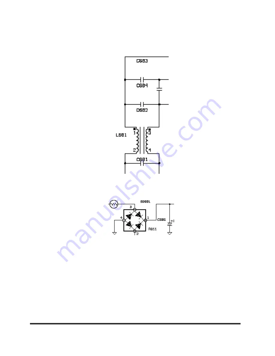
(a) EMI Filter
This circuit (fig. 2) is designed to inhibit electrical and magnetic interference for meeting FCC, VDE,
VCCI standard requirements.
Fig. 2
(b) Rectifier and filter
AC Voltage (90-264V) is rectified and filtered by BD601, C605 (See Fig 3) and the DC Output
voltage is 1.4*(AC input). (See Fig.3)
Fig. 3
(c) Switching element and Isolation power transformer
When the Q601 turns on, energy is stored in the transformer. During Q601 turn-off period, the stored
energy is delivered to the secondary of transformer. R607, C607 and D601 is a snubber circuit. R615 is
current sense resistor to control output power. (See Fig.4)
Summary of Contents for DV172
Page 22: ...DV172 LCD Monitor Service Guide Circuit Operation Theory 8 ...
Page 31: ...DV172 LCD Monitor Service Guide Alignment procedure 5 b Speaker wire ...
Page 32: ...DV172 LCD Monitor Service Guide Alignment procedure 6 c LVDS wire d Power grounding ...
Page 41: ...3 94 53 L5304 001 F DISK MEA DV172 ...
Page 45: ......
Page 46: ......


