23
The sensor is adjusted and calibrated at the factory, but could require adjustment and/or calibration
if the sensor bracket is bent or moved, or pulley wear/replacement changes its relative position to
the wire. At no time should the cutting wire be in direct contact with the
sensor face.
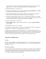
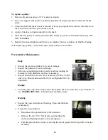
Adjust the sensor vertically so that the cutting wire marks a chord 2mm
(0.08in) above the center of the circular face. From behind the saw, loosen
the set screw locking the sensor mount to the pulley shaft with a 3/32 hex
wrench, rotate the sensor bracket into position, and re-tighten.
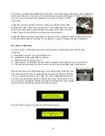
Adjust the distance between the sensor face and the wire to slightly less that 0.5mm (about .02in).
This adjustment could be necessary if you change to a larger or smaller diameter cutting wire.
Bow Sensor Calibration
The bow sensor is calibrated at the factory but should be recalibrated under the following
conditions:
a) Installation of a new wire of a different size,
b) Adjustment of the guide pulleys spacing,
c) Significant observed inaccuracy,
d) The message, "WARNING: Bow Not Zero" appears even though the wire is not bowed,
e) Physical repositioning of the bow sensor for any reason, including pulley replacement.
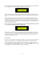
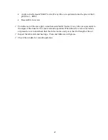
Place the Bow Sensor Calibration Gage on the cutting table, under the wire
and centered between the two guide pulleys. Jog the yoke down so that the
wire just contacts the peak of the wedge. It is rather important that there be
no bow at this point Once the wire contacts the wedge, do not move it. You
do not want to accidentally shift the wire forward or backward in its cutting
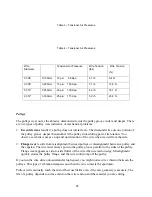
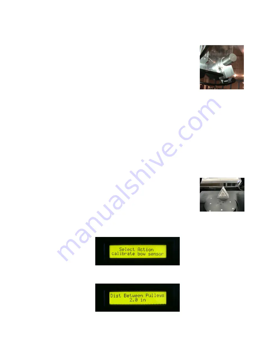
plane. Enter the calibration function from the jog menu.
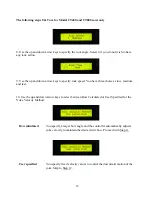
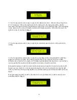
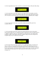
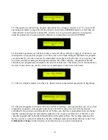
Press the right arrow key to begin the calibration sequence.

