2
Electrical and Pneumatic Connections
The Saw requires 115 volt 50/60 Hz, single-phase power. Plug the controller power cord into a 15
Amp grounded outlet.
Connect the saw to a source of dry, lubricated air delivering
at least 80psi.
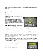
Connect the STEPPERS, SENSORS, and CAPSTAN
cables to their corresponding connectors on the right side of
the saw. The black cable connects to the lower receptacle
with the rotating ring. The two gray cables connect to the
flange mount receptacles. Each of the three connectors is of
a different pin configuration to ensure a correct connection.
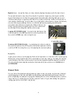
There is an auxiliary (
AUX)
output connector on the back of the controller that can be used to
signal or power a sprayer, slurry pump, or relay. The output signal is 120VAC at 1.5 Amps. The
output is active whenever the wire drive is in operation. The connector, AMP 206429-1, is
available from several electronic suppliers.
Drain Connection
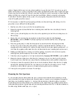
The base of the saw is designed to contain cutting lubricant if your
application calls for it
.
Two 3/8” push-to-connect fittings, located
on the rear of the saw should be plumbed with a drain hose to
carry away excess fluids. An overflow slot is cut near and above
the drain. Do not block this overflow. If liquid is allowed to rise
above the overflow, it could flow into the table bearings or the
table drives motor and cause permanent damage to the machine.
Spray System
(Optional)
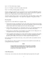
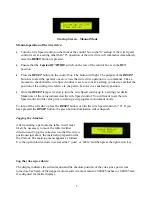
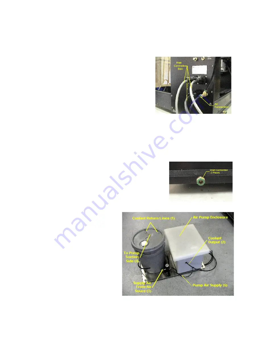
Place the coolant pump pallet as close to
the saw as possible, preferably directly
underneath the saw. Follow the diagram
for making the proper connections for
water and air to the saw.
Item 1 - 3/8” tubes to connect to the lower
rear of saw. These are the coolant drain
lines.
Item 2 – 1/4” tubing to connect to the ¼
”
Tee located on the rear of the Rocker
plate.


