background image

A010322  Rev. 2 

Pagina 6 di 16


6.2 Electrical connections 

Connections  must  be  made  in  accordance  with  the  local  standards  in  force.  The equipment’s electric circuit is designed to work with a 
single-phase supply voltage of 230 Volts and a frequency of 50 Hz. 
The equipment is connected by means of the power cable D (Fig. 2) which comes out of an opening at the bottom of the upright. 
The cable must have the features of type H05 RNF or better, and must feature an efficient earth wire of an appropriate size for the total 
power of this unit and any other units or accessories connected on the same terminal board (see rating plate)
The unit’s electrical supply system must feature an appropriately sized automatic omnipolar circuit breaker upstream that assures a gap 
between the contacts of at least 3mm. There must not be any breaks in the earth cable. 
 
The electrical safety of this equipment is only assured when the above-mentioned conditions are met. 
 
NOTE:  This  unit  has  a  “Y”  electrical  connection  and,  therefore,  if  the  power  cable  is  every  replaced,  the  work  must  be 
performed by a qualified electrician ONLY. 
The manufacturer declines all responsibility in the event these safety standards are not complied with. 

7. OPERATION / USE 

7.1 Operating tips  


Avoid placing hot foods or evaporating liquids inside the unit. 


Only keep the doors open for as long as it takes to put the food inside or take it out. 


Do not cover the top of the unit as this might impede the flow of air. 


Before using the equipment for the first time, clean it inside with lukewarm water and neutral soap. Avoid using abrasive detergents or 
scouring powders. Lastly, rinse and dry thoroughly. 

7.2 Starting up 


Turn on the circuit breaker located upstream from the equipment. 


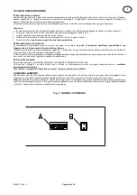
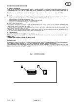
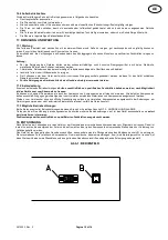
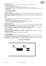
Switch on the digital thermostat A of Fig.1  by pressing the buttom 4 for at least 5” time (see picture) 


If  the  temperature  in  the  refrigerated  unit  is  higher  than  the  thermostat  value,  the  compressor  starts  working  and  the  thermostat’s  
LED 6 comes on. 


The lighting inside the showcase is switched on by pressing switch B

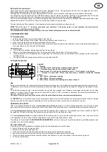
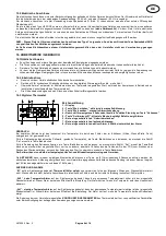
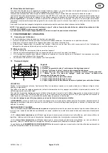
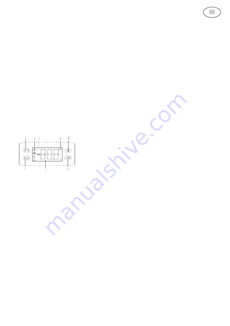
7.3 Digital thermostat 


Legend 

1 – Display 
2 – “Increase value” push button, activates manual defrost 
3 –  “Decrease value” push button, manual alarm reset 
4 – Press at least 5” to activate the stand-by function -  “Exit function” push button 
5  –    “Access  set  point  push  button,  accesses  menus,  confirms  commands,  displays 
alarms 
6 – Red LED on, compressor running 
7 – Red LED on, defrost in progress
 
8 – Red LED on,  alarm active, flashing when alarm silenced 

 
USE 
During normal operation, the instrument displays the temperature measured in the refrigerated area (showcase basin/top, compartment). 
To display the current set point (selected temperature), press and release the key  set, the message "set will appear, press again the key 
set
To  modify  the  working  set  point,  press  and  release  the  key  set,  the  message  "set  will  appear,  press  again  the  key  set,  the  set  value 
appears,  to  modify  it  within  15  seconds  use  the  push  buttons 

▲(2)  or  ▼(3)  to  increase  or  decrease  the  value;  after  modificati

on,  to 

memorize, again press the key  set
The set point can be given any of the values within the established minimum and maximum temperature 
 
The DEFROST can be activated at any time by pressing the key

▲ (2) for at least 5 seconds; the next automatic defrost will occur starting 

from this time after the time lapse for defrosting set by the manufacturer (factory set at 6 hours, and lasts 15 minutes). 
 
WARNINGS AND ALARMS 
 ‘E1’  on  the  display  indicates  that  the    thermostat  probe  is  faulty  indicating  one  of  the  following  anomalies:  incorrect  type  of  basin 
probe, defective probe, defective connections; check the condition of the probe and correct connection between instrument and probe.       
 
“AH1” high temperature alarm on display indicates that the reading value is higher then  the presetted max. value; it causes no effect to 
the regulation, the alarm stops when the temperature decreases under the presetted max. value. 
 
“AL1” low temperature alarm on display indicates that the reading value is lower then the presetted minimum value, it causes no effect 
to the regulation, the alarm stops when the temperatures rises over the presetted minimum value. 


The editing of the thermostat’s CONFIGURATION PARAMETERS, which are factory set, must be performed by qualified personnel only 
according to the instructions attached. 

7.4 Total switch-off 

When the unit is to be mothballed for a lengthy period, the following measures must be taken: 


Switch off the unit with the master switch. 


Disconnect the power supply upstream. 


Remove all the food from the showcase and clean the inside as well as all the accessories. 


Leave the doors ajar so that fresh air can get inside, preventing undesirable smells from forming. 


Protect the stainless steel surfaces by smearing them with Vaseline oil: use a cloth soaked in the oil and rub vigorously. 


Air the room periodically 


GB


Summary of Contents for 8046041

Page 1: ...Mod IN VTAF15 Production code 8046041 03 2017 ...

Page 2: ...ER VETRINE ESPOSITRICI REFRIGERATE INSTALLATION OPERATING AND MAINTENANCE MANUAL FOR REFRIGERATED SHOWCASES INSTALLATIONS BEDIENUNGS UND WARTUNGSANLEITUNG FÜR GEKÜHLTE AUSSTELLUNGSVITRINEN NOTICE D INSTALLATION UTILISATION ET ENTRETIEN POUR VITRINES D EXPOSITION REFRIGEREES I GB DE FR ...

Page 3: ...a su pallet deve essere scaricata mediante carrello elevatore o altro macchinario di sollevamento idoneo manovrati da personale addestrato Il peso massimo è indicato in Tabella A Eventuali errori di manovra potrebbero causare infortuni per schiacciamento Qualora le superfici dell apparecchiatura subissero urti esse sarebbero immediatamente rovinate In questa fase deve essere vietata la sosta nelle...

Page 4: ... menu conferma comandi visualizza allarmi 6 Led rosso acceso compressore acceso 7 Led rosso acceso sbrinamento in corso 8 Led rosso acceso allarme attivo lampeggiante per allarme tacitato USO Nel corso del normale funzionamento lo strumento visualizza la temperatura rilevata dalla sonda posta nell ambiente refrigerato vetrina vasca piano vano Per visualizzare l attuale valore del set point valore ...

Page 5: ...e In questo ambito possono essere necessarie riparazioni o sostituzioni Le parti difettose devono essere sostituite solo con materiali e componenti identici a quelli originali o indicati dal Fornitore In caso di sostituzione di componenti o modifica sull apparecchiatura eseguita dall utilizzatore senza il consenso scritto del Costruttore o con ricambi non autorizzati la garanzia decade immediatame...

Page 6: ... at all 4 TRANSPORTATION AND HANDLING If the equipment is transported on a pallet it must be unloaded using a lift truck of other appropriate lifting means operated by trained personnel The maximum weight is given in Table A Manoeuvring errors might cause injury as a result of crushing Any knocking of the surfaces of the equipment will result in immediate damage During this phase anyone not direct...

Page 7: ...ses menus confirms commands displays alarms 6 Red LED on compressor running 7 Red LED on defrost in progress 8 Red LED on alarm active flashing when alarm silenced USE During normal operation the instrument displays the temperature measured in the refrigerated area showcase basin top compartment To display the current set point selected temperature press and release the key set the message set wil...

Page 8: ...wer mains In this case repairs or replacements might be required The faulty parts must only be replaced with materials and components identical to the originals or specified by the Manufacturer The replacement of components or the modification of the equipment by the user without written permission from the Manufacturer or the use of non authorized spare parts shall instantly cause the warranty to...

Page 9: ...sehen sind 13 TRANSPORT UND WEITERBEFÖRDERUNG Wird das Gerät auf Paletten transportiert ist dieses mittels eines Gabelstaplers oder anderen Hebewerken die von dazu befähigtem Personal zu bedienen sind abzuladen Das Höchstgewicht ist in der Tabelle A angegeben Eventuelle Manövrierfehler könnten zu schweren Körperverletzungen Quetschungen führen Die Oberflächen des Gerätes sind ausreichend gegen Stö...

Page 10: ...Thermostat Zeichenerklärung 1 Display 2 Taste Wert erhöhen aktiviert die manuelle Abtauung 3 Taste Wert senken manuelle Alarmrücksetzung 4 Gedrückt für wenigstens 5 Sekunden lässt die Funktion Stand by an Taste Verlassen 5 Taste Sollwertzugriff öffnet die Menüs bestätigt Befehle zeigt Alarme 6 Rote eingeschaltete Led Heizwiderstand an 7 Rote eingeschaltete Led laufende Abtauung 8 Rote eingeschalte...

Page 11: ...werden 17 2 Instandsetzung Eventuell auftretende Betriebsstörungen dürfen ausschließlich von qualifizierten Fachkräften behoben werden nach Möglichkeit ist das Gerät zuvor vom Stromnetz zu trennen Es können sich sowohl Reparaturen als auch der Austausch von Komponenten als erforderlich erweisen Alle defekten Komponenten dürfen ausschließlich gegen gleichwertige oder vom Hersteller empfohlene Mater...

Page 12: ... levage adapté manoeuvré par du personnel entraîné Le poids maximum est indiqué dans le Tableau A D éventuelles erreurs de manoeuvre pourraient causer des accidents par écrasement Au cas où les surfaces de l appareil auraient subi des chocs elles seraient immédiatement abîmées Pendant cette phase le stationnement à proximité doit être interdit à toute personne qui n est pas directement concernée p...

Page 13: ...tat digital Légende 1 Afficheur 2 Bouton augmenter la valeur actionnement du dégivrage manuel 3 Bouton diminuer la valeur remise à zéro manuelle des alarmes 4 Pousser min 5 sec pour activer la fonction stand by Bouton fonction de sortie 5 Bouton accès à la valeur de réglage accès aux menus validation des commandes affichage des alarmes 6 Voyant rouge allumé compresseur allumé 7 Voyant rouge allumé...

Page 14: ...e l alcool et avec un chiffon humide Durant le nettoyage ne pas laver l appareil avec des jets d eau 8 2 Entretien extraordinaire L entretien extraordinaire a lieu en cas de panne ou d anomalie de la part de personnel qualifié si possible avec l appareil débranché du réseau d alimentation Dans ce cadre des réparations ou des remplacements peuvent être nécessaires Les parties défectueuses doivent ê...

Page 15: ... Supply voltage 50 Hz V 230 230 230 230 Total power kW 1 2 1 2 1 2 1 2 Max weight Kg 135 125 155 145 Tabelle A TECHNISCHE MERKMALE GEKÜHLTE AUSSTELLUNGSVITRINEN TECHNISCHE DATEN Modell MIT ISOLIERTER ABSTELLFLÄCHE OHNE ISOLIERTE ABSTELLFLÄCHE MIT ISOLIERTER ABSTELLFLÄCHE OHNE ISOLIERTE ABSTELLFLÄCHE Außenmaße L Länge mm 1180 1180 1480 1480 P Tiefe mm 640 640 640 640 H Höhe mm 1150 1150 1150 1150 T...

Page 16: ...A010322 Rev 2 Pagina 15 di 16 Fig 2 SCHEMA DI INSTALLAZIONE INSTALLATION DIAGRAM INSTALLATIONSSCHEMA SCHEMA D INSTALLATION ...

Page 17: ...LATOR KONDENSATOR M3 MOTORVENTILATOR VERDAMPFER Nv NEONLAMPEN VITRINE Mn KLEMMENBRETT NEONLAMPEN E E VENTIL E VENTI X1 KLEMMENBRETT 230 V EINPHASIG 50 Hz Ig MASTER REFRIGERATION SWITCH GREEN F RADIO INTERFERENCE SUPPRESSOR In SHOWCASE LIGHTING LUMINOUS SWITCH Pr SAFETY PRESSURE SWITCH Tt SHOWCASE TELETHERMOSTAT M1 COMPRESSOR M2 CONDENSER MOTOR DRIVEN FAN M3 EVAPORATOR MOTOR FAN Nv SHOWCASE NEON LI...

Reviews: