8
Assembly Instructions (Continued)
Then, slide the entire seat frame into the rear end of the seat track channel while holding the seat
frame adjusting handle up, making sure the three rollers on each side of the seat frame assembly
are inside the channel. Then, release the adjusting handle to lock the seat frame in position.
Replace the seat bumper and re-tighten the bolt.
5-3.
Replace the rear endcap and re-tighten the two screws.
5-4.
Connect the plug from the hand pulse wiring harness on the seat handlebar to the jack on the re-
5-5.
tracting cable hanging out of the sidecase.
Pull the harness thru the L-shaped slot in the seat frame and secure it onto the side of the seat
5-6.
frame using the included nylon zip tie (see illustration 5-6 in assembly drawing).
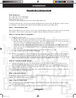
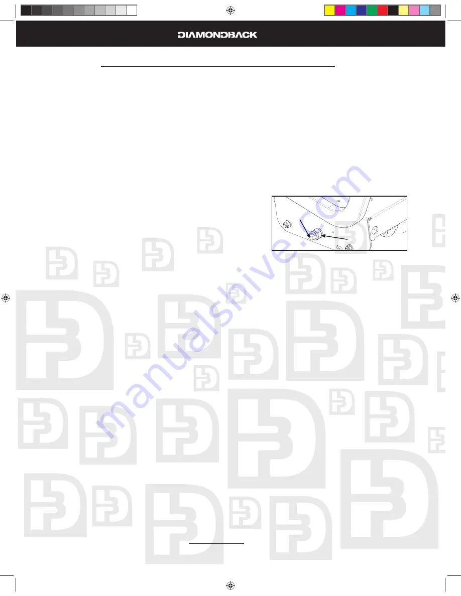
Tighten the seat frame on to the seat track so that it does not “wobble” side to side. This can be
5-7.
done by adjusting the middle seat rollers on each side of the seat frame as shown in the picture
below.
Find the middle seat roller adjustment on the right side
a.
of the seat frame (under the seat) as shown in the pic-
ture.
While using an open-end wrench to hold the adjustment
b.
knob, loosen the seat roller nut by turning it counter-
clockwise with a second open-end wrench.
Tighten the seat frame into the seat track by turning the
c.
adjustment knob clockwise. Do not overtighten as this
may prevent the seat from sliding along the track.
Hold the adjustment knob in position with one wrench while you re-tighten the seat roller nut
d.
with the second wrench.
Repeat steps a-d above with the middle seat roller adjustment on the left side of the seat frame
e.
The seat should now slide easily along the seat track without “wobbling” side to side.
Note: The middle seat rollers may need to be readjusted periodically as they wear.
Install seat pad on the seat frame using the four M6 x 60mm screws, making sure to include a fl at
5-8.
and split lock washer on each bolt.
Install seat back pad on the seat frame using the four M6 x 15mm screws, making sure to include a
5-9.
fl at and split lock washer on each bolt.
Step 6: Pedal Assembly
Use a 15mm or adjustable open-end wrench to fi rmly tighten the pedals to the cranks. The left and right
pedals are different and are denoted as right or left (R or L) on the top & bottom of each pedal. Note
that the left pedal will thread counter-clockwise.
Note: Pedals should be re-tightened after the fi rst 10 hours of use as they may become loose until they have
fully seated to the crank.
Step 7: Power Adapter
Plug DC adapter into the power jack located on the front of the unit near the bottom.
7-1.
Plug the adapter into a power outlet.
7-2.
Seat roller
nut
Seat roller
adjustment
1000Sr OM.indd 8
1000Sr OM.indd 8
7/7/2008 2:27:57 PM
7/7/2008 2:27:57 PM
Summary of Contents for 1000SR
Page 5: ...6 Assebly Drawing 1000Sr OM indd 6 1000Sr OM indd 6 7 7 2008 2 27 54 PM 7 7 2008 2 27 54 PM ...
Page 37: ...38 Notes 1000Sr OM indd 38 1000Sr OM indd 38 7 7 2008 2 28 11 PM 7 7 2008 2 28 11 PM ...
Page 38: ...39 Notes 1000Sr OM indd 39 1000Sr OM indd 39 7 7 2008 2 28 11 PM 7 7 2008 2 28 11 PM ...


