


IntelliAg PDC User Level 1
11001-1510-200904
i
TABLE OF CONTENTS
Introduction .......................................................................................................... 1
Features............................................................................................................................. 1
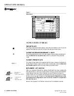
Main Work Screen ............................................................................................................. 1
Work Screen Symbols ....................................................................................................... 2
Target Rate ....................................................................................................................................... 2
Target Increase/Decrease % Rate.................................................................................................... 2
Target Preset Rate............................................................................................................................ 2
Implement Lift Switch ........................................................................................................................ 2
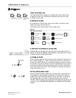
Task Controller.................................................................................................................................. 3
Row Indicators .................................................................................................................................. 3
Autopilot Steering Navigation............................................................................................................ 3
Accumulators .................................................................................................................................... 3
Population Row Scan........................................................................................................................ 3
Singulation Average Population ........................................................................................................ 4
Material Name................................................................................................................................... 4
Population Max Row ......................................................................................................................... 4
Population Min Row .......................................................................................................................... 4
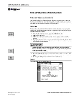
Pre-Operating Preparation .................................................................................. 5
Pre-Defined Constants ...................................................................................................... 5
Fill Disk.............................................................................................................................................. 5
System Operation ................................................................................................ 7
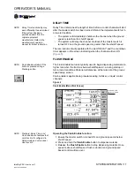
Start ................................................................................................................................... 7
Stop ................................................................................................................................... 7
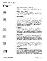
Operate Function Buttons.................................................................................................. 8
Master Switch On/Off ........................................................................................................................ 8
Next Channel .................................................................................................................................... 8
Increment .......................................................................................................................................... 8
Decrement......................................................................................................................................... 8
Inc/Dec Reset to Target .................................................................................................................... 8
Turn On/Off Channel......................................................................................................................... 8
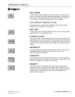
Next Screen ...................................................................................................................................... 9
Non Operate Mode Buttons ............................................................................................... 9
Next Page ......................................................................................................................................... 9
Planter Fill Disk ................................................................................................................................. 9
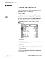
Diagnostics........................................................................................................................................ 9
Alarm Log.......................................................................................................................................... 9
Summary........................................................................................................................................... 9
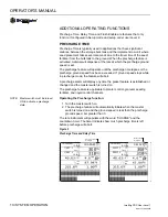
Additional Operating Functions........................................................................................ 10
Precharge Time............................................................................................................................... 10
Delay Time ...................................................................................................................................... 11
Flush Enable ................................................................................................................................... 11
Summary of Contents for IntelliAg
Page 8: ...OPERATOR S MANUAL IntelliAg PDC User Level 1 11001 1510 200904 6 PRE OPERATING PREPARATION...
Page 14: ...OPERATOR S MANUAL IntelliAg PDC User Level 1 11001 1510 200904 12 SYSTEM OPERATION...
Page 22: ...OPERATOR S MANUAL IntelliAg PDC User Level 1 11001 1510 200904 20 TROUBLESHOOTING ALARMS...
Page 30: ...OPERATOR S MANUAL IntelliAg PDC User Level 1 11001 1510 200904 28 TROUBLESHOOTING ALARMS...


