


OPERATOR’S MANUAL
IntelliAg PDC User Level 1
11001-1510-200904
TROUBLESHOOTING & ALARMS / 27
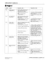
264
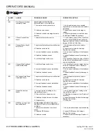
Ground Speed Calibration
Calibration Configuration
Alarm
Current ground speed calibration exceeds
the max number of ground speed pulses of
50000 that can be entered as a ground
speed constant.
1. Probable that the marked off course
limits were exceeded. Verify course length
of 400 ft (100 m).
2. Ground speed sensor has too high
resolution of pulses. Check speed sensor
for damage.
602
8 Volt Supply Failure
Alarm
8V SUPPLY VOLTAGE IS BELOW 7.2V
OR HIGHER THAN 16V.
1. Damaged module harness.
2. Defective seed or hopper sensor.
3. Defective module.
1. Inspect module harness for damage.
Repair or replace harness.
2. Inspect seed or hopper sensors
connected to the identified module for
damage. Replace sensors if necessary.
3. Replace identified module.
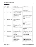
603
Member Module
Communication Failed
Alarm
COMMUNICATION WITH AN ACTIVE
MODULE HAS FAILED
1. Damaged CAN or module harness.
2. Blown module harness fuse.
3. Defective module.
1. Identify missing module in the Module
Configuration list. Inspect CAN/module
harness of the missing module for damage.
Repair or replace harness.
2. Inspect module harness fuse, replace if
necessary.
3. Identify missing module in the Module
Configuration list. Inspect missing module
for damage or replace.
604
ECU Voltage Out of
Range Alarm
ECU VOLTAGE IS BELOW 11V OR
HIGHER THAN 16V.
1. Damaged CAN or module harness.
2. Defective module
1. Inspect CAN/module harness of the
identified module for damage.
2. Inspect identified module for damage or
replace.
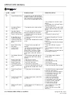
605
Solenoid Voltage Out of
Range Alarm
SOLENOID VOLTAGE IS BELOW 11V OR
HIGHER THAN 16V.
1. Damaged CAN or module harness.
2. Blown module harness fuse.
3. Defective module.
1. Inspect CAN/module harness of the
identified module for damage. Repair or
replace harness.
2. Inspect module harness fuse or replace.
3. Inspect identified module for damage or
replace.
606
Ground Offset Voltage
Out of Range Alarm
1. Damaged/shorted Actuator Harness.
2. Defective PWM valve driver or Servo
valve driver.
3. Defective module.
1. Inspect Actuator Harness for damage
around the WPM and Servo valve
connections. Repair or replace harness.
2. Inspect PWM or Servo valve drivers for
damage and replace if necessary.
3. Inspect identified module for damage
and replace if necessary.
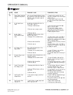
607
Task Controller Task
Stopped Alarm
1. Control rates no longer set by Task
Controller.
1. Press TC RATE to keep the last target
rate from the Task Controller.
2. Press MAT RATE to use the target rate
from the material setup.
608
Task Controller Data
Logging Error
1. Task Controller is setting target rates
without logging the data.
1. Restart Task Controller task.
2. Cycle power to entire system.
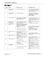
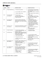
ALARM
#
ALARM
PROBABLE CAUSE
CORRECTIVE ACTION
Summary of Contents for IntelliAg
Page 8: ...OPERATOR S MANUAL IntelliAg PDC User Level 1 11001 1510 200904 6 PRE OPERATING PREPARATION...
Page 14: ...OPERATOR S MANUAL IntelliAg PDC User Level 1 11001 1510 200904 12 SYSTEM OPERATION...
Page 22: ...OPERATOR S MANUAL IntelliAg PDC User Level 1 11001 1510 200904 20 TROUBLESHOOTING ALARMS...
Page 30: ...OPERATOR S MANUAL IntelliAg PDC User Level 1 11001 1510 200904 28 TROUBLESHOOTING ALARMS...


