background image

OPERATOR’S MANUAL

Seed Manager SE ®

11001-1359A-200810

/I

Safety Notices ..................................................................................................... 1

Introduction ......................................................................................................... 3

System Overview .............................................................................................................. 3

Installation and Setup ......................................................................................... 5

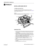
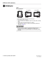
Console Mounting ............................................................................................................. 5
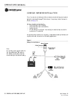
Console Harness Installation ............................................................................................ 6
Power Connection ............................................................................................................. 7
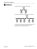
Implement Harness/Module Connection ........................................................................... 9

Module Order ................................................................................................................................... 9
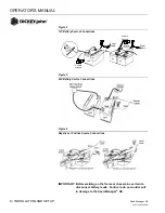
Module Installation ........................................................................................................................... 9
Module Setup Examples ................................................................................................................ 12
Connecting Sensors to Modules .................................................................................................... 14
Hopper Level Sensors .................................................................................................................... 15

Harnesses ....................................................................................................................... 18

12 Row Harness ............................................................................................................................. 18
16 Row Harness ............................................................................................................................. 18
Shaft Speed Module Harness ........................................................................................................ 19
RS485 Extension Harness ............................................................................................................. 19

Startup ............................................................................................................... 21

Switchpad Overview ....................................................................................................... 21

On/Off ............................................................................................................................................. 21
Alarm .............................................................................................................................................. 21
Setup .............................................................................................................................................. 21
Min Avg Max Scan ......................................................................................................................... 21
Select Row ...................................................................................................................................... 21
Select .............................................................................................................................................. 22
Set................................................................................................................................................... 22
Start Stop Reset ............................................................................................................................. 22
Back ................................................................................................................................................ 22
Operate 1 ....................................................................................................................................... 22
Operate 2 ....................................................................................................................................... 23
Operate 3 ....................................................................................................................................... 23

Setup Mode ..................................................................................................................... 24

Setup Constants ............................................................................................................................. 24
Seed Flow Alarm Adjustment ......................................................................................................... 26
Population Hi Limit ......................................................................................................................... 27
Population Lo Limit ......................................................................................................................... 27
Row Width ...................................................................................................................................... 27
Implement Width ............................................................................................................................ 28
Ground Speed Source ................................................................................................................... 28
Distance Calibration ....................................................................................................................... 28
Automatic Configuration ................................................................................................................. 29
Split Row Configuration .................................................................................................................. 30
Number of Seed Modules .............................................................................................................. 31
Row Status ..................................................................................................................................... 32
Total Number Of Rows Configured ................................................................................................ 33
Number of Fan Speed Sensors ...................................................................................................... 33
Number of Shaft Speed Sensors ................................................................................................... 35

Summary of Contents for seed manager

Page 1: ...Speed Module Harness 19 RS485 Extension Harness 19 Startup 21 Switchpad Overview 21 On Off 21 Alarm 21 Setup 21 Min Avg Max Scan 21 Select Row 21 Select 22 Set 22 Start Stop Reset 22 Back 22 Operate 1...

Page 2: ...t Row 47 Seed Spacing 48 Ground Speed 48 Fan Speed 49 Shaft Speed 49 Pressure 50 Area Accumulator 50 Seed Count 51 Distance Accumulator 51 Speed Area Mode 52 Alarms 53 All Rows Failed 54 Rows Failed 5...

Page 3: ...follows Be alert to the possibility of personal injury or death Use of the word WARNING indicates a potentially hazardous situation which if not avoided could result in death or serious injury Use of...

Page 4: ...OPERATOR S MANUAL Seed Manager SE 11001 1359A 200810 2 SAFETY NOTICES...

Page 5: ...ws two 2 fan RPM inputs three 3 shaft speed RPM inputs two 2 pressure inputs seven 7 hopper level inputs and 1 ground speed input It is compatible with DICKEY john standard and Hi Rate seed sensors Im...

Page 6: ...OPERATOR S MANUAL Seed Manager SE 11001 1359A 200810 4 INTRODUCTION...

Page 7: ...a template to mark the two outside holes of the bracket on the selected location and drill two 9 32 inch holes An alternate mounting method that allows the console to swivel requires drilling the cent...

Page 8: ...ound speed sensor digital Ground speed sensor reluctance System power P1 and P2 Bus connectors A secondary module harness is used to connect to P1 and or P2 For systems that contain a J2 connector a s...

Page 9: ...or Harnessing Power connections should be made last to avoid accidental shorts during harness installation POWER CONNECTION The Seed Manager SE System operates on 12 volts DC only The battery connecti...

Page 10: ...ure 5 24V Battery Source Connections Figure 6 Negative or Positive Source Connections IMPORTANT Before welding on the frame or chassis be certain to disconnect battery leads Failure to do so could res...

Page 11: ...dules are connected and their position on the toolbar or implement is important The Material Flow Modules are identified by the console as b1 b2 bn where n is the total number of Material Flow Modules...

Page 12: ...o a frame Use the enclosure as a template to mark the location of the mounting holes Drill two 9 32 inch diameter holes where marked Attach to frame using 1 4 x 20 bolts or other fastening devices as...

Page 13: ...igure 9 If necessary drill mounting holes following the procedure described above Securely tighten tie strap Install a second tie strap toward the label end of the enclosure for additional support Fig...

Page 14: ...nsor Select the mounting location and install as described in the instructions 8 Connect each module together with a bus harness IMPORTANT Be sure the locking tabs engage when inserting the connectors...

Page 15: ...up one module connected to both P1 and P2 Two Module Setup three modules connected to PA and 2 connected to P2 As the previous examples show b1 is always identified as the LAST module connected to P1...

Page 16: ...aterial Flow Modules all seed sensors installed on a Material Flow Module must be connected sequentially starting with Row 1 as shown below When correctly connected row 1 sensor should be connected to...

Page 17: ...s on a Material Flow Module The monitor will identify the number of hopper sensors connected to each Material Flow Module and will number them from 1 to n starting with any sensors connected to b1 If...

Page 18: ...the bus If the Shaft Speed Module is connected to the RS 485 out of b1 the numbering of the hopper sensors starts with this module then continues with any hopper sensors connected to b1 b2 etc If the...

Page 19: ...can only be connected to the Shaft Speed Module These sensors are identified by the monitor according to what input they are connected to regardless of the position of the Shaft Speed Module on the bu...

Page 20: ...OPERATOR S MANUAL Seed Manager SE 11001 1359A 200810 18 INSTALLATION AND SETUP HARNESSES 12 ROW HARNESS 16 ROW HARNESS...

Page 21: ...OPERATOR S MANUAL Seed Manager SE 11001 1359A 200810 INSTALLATION AND SETUP 19 SHAFT SPEED MODULE HARNESS RS485 EXTENSION HARNESS...

Page 22: ...OPERATOR S MANUAL Seed Manager SE 11001 1359A 200810 20 INSTALLATION AND SETUP...

Page 23: ...edges the alarm condition Additionally holding the switch pressed for more than one 1 second allows the volume level of the alarm to be adjusted As the switch is pressed the alarm sounds continuously...

Page 24: ...Distance Accumulator functions to start or stop the accumulations It is also used in Setup Mode Distance Calibration Automatic Configuration and Sensor Self Test functions to start or stop the test Ot...

Page 25: ...Selects Fan Speed Shaft Speed or Pressure Mode if available on system Successive presses of the switch will change to the next mode OPERATE 3 Selects Area Seed Count or Distance Accumulator Mode Succ...

Page 26: ...ng the SET switch increases the selected digit by one count After reaching the maximum value of nine 9 the digit rolls over to zero 0 Press the START STOP RESET to set the digits to zero Pressing the...

Page 27: ...umber of Rows Configured N A 01 96 13 Number of Fan Speed Sensors 0 0 2 13A Fan Speed Sensor 1 Constant 000 0 000 0 999 99 13B Fan Speed Sensor 1 Hi Limit 00065 00000 99999 13C Fan Speed Sensor 1 Lo L...

Page 28: ...value is 00 which requires a minimum seed flow of at least 2 seeds per second before row failure alarm activates The maximum value allowed is at least 1 seed every 10 seconds Figure 17 indicates a mi...

Page 29: ...eeds acre Figure 18 Population Hi Limit Display 3 POPULATION LO LIMIT When the population on any row falls below the value entered for this constant in thousands of seeds per acre hectare the alarm so...

Page 30: ...ground speed sensor is used and is connected directly to the Seed Manager Console press the SET switch until d1 appears If a digital radar or Hall Effect type ground speed sensor is used and is connec...

Page 31: ...time then enter the average as the Distance Calibration Constant using the SELECT and SET switches 8 AUTOMATIC CONFIGURATION To Begin the Automatic Configuration 1 Press the START STOP RESET switch Th...

Page 32: ...a row pattern of 01 being selected Figure 25 Split Row Configuration Split Row Configuration Description Example 00 All Row s On 01 Every other row OFF w ith first row ON OXOXOX 02 Every other row OF...

Page 33: ...ctual number of seed modules Figure 27 shows a configuration for six 6 modules Figure 27 Seed Modules Display 10A E Number of Seed Sensors Per Module For each seed module that is configured on the pre...

Page 34: ...implement OFF status turns off the related sensors so alarms do not occur The display initially shows the messages SETUP ROW 1 and the status of row 1 Figure 29 shows row 7 status set to OFF Press th...

Page 35: ...display for sixteen 16 rows NOTE Use Figure 16 Setup Mode Parameters as reference for the following items numbered 1 21 Figure 30 Rows Configured Display 13 NUMBER OF FAN SPEED SENSORS This is the act...

Page 36: ...eed Sensors has a value other than 0 Figure 32 shows the display with a Fan Speed Constant of 34 00 pulses per revolution Figure 32 Fan Speed Constant Display 13B and 13E Fan Speed Sensor Hi Limit Thi...

Page 37: ...between ON and OFF Figure 34 shows a limit of 25 RPM with the warning disabled NOTE Use Figure 16 Setup Mode Parameters as reference for the following items numbered 1 21 Figure 34 Lo Limit Fan Speed...

Page 38: ...Number of Shaft Speed Sensors has a value other than 0 Figure 36 shows the display with a Shaft Speed Constant of 26 00 pulses per revolution Figure 36 Shaft Speed Constant Display 14B 14E and 14H Sh...

Page 39: ...igit then press the SET switch to toggle between ON and OFF Figure 38 shows a limit of 12 RPM with the warning disabled NOTE Use Figure 16 Setup Mode Parameters as reference for the following items nu...

Page 40: ...mit The Pressure Sensor Hi Limit Warning is entered in oz in2 kPa The hi and lo warning limits are accessible only if the Number of Pressure Sensors has a value other than 0 Setting the Pressure Senso...

Page 41: ...of 3 8 with the warning disabled NOTE Use Figure 16 Setup Mode Parameters as reference for the following items numbered 1 21 Figure 42 Lo Limit Pressure Display 17 BLOCKAGE MODE CONFIGURATION This con...

Page 42: ...uations in population and spacing that are undesirable The population filtering option applies an averaging filter to the population and spacing calculations The filter values range from 0 to 99 with...

Page 43: ...gure 46 Population Scaling Display 20 SENSOR MODULE SELF TEST Start the test by pressing the START STOP RESET switch The TEST message flashes while the test is executing Note This is the same test tha...

Page 44: ...advance to the next Customer Setup Constant To exit the Customer Setup Constants power off the console The different Customer Setup Constants are listed as follows Figure 49 Boot Number Display Boot...

Page 45: ...it number shows on the upper numeric display at the same time an F1 identifier appears on the lower numeric display Record this number then press and release the SELECT switch to step to the F2 F3 and...

Page 46: ...OPERATOR S MANUAL Seed Manager SE 11001 1359A 200810 44 STARTUP...

Page 47: ...ered Run Hours are not accumulated during an ALL ROWS FAILED condition or if a lift switch is installed and the implement is in the up position The Run Hours total is displayed for five 5 seconds imme...

Page 48: ...f five 5 dashes and no population values will be available The Population display has several different modes based upon the Setup configuration and the scan mode that is selected A short description...

Page 49: ...population of 152 300 seeds acre on row five 5 Figure 54 Population Min Avg Max Display POPULATION SELECT ROW Depressing the SELECT ROW switch while in either Population Scan or Population Min Avg Max...

Page 50: ...e Setup configuration and the scan mode that is selected and they are the same modes as in the Population function Figure 56 shows an implement average seed spacing of 2 3 inches between seeds Figure...

Page 51: ...numerical display Figure 58 shows a fan speed of 275 8 RPM Figure 58 Fan Speed Display SHAFT SPEED This is the rotational speed of a shaft A Hall Effect type sensor senses a multi toothed gear mounte...

Page 52: ...solution as Area Accumulator 1 and 2 The area calculations are based on the implement width and distance traveled Area does not accumulate during an ALL ROWS FAILED condition i e when the implement is...

Page 53: ...ed Count is running without affecting the actual seed counts Figure 62 shows a stopped seed counter with 1693 seeds counted on row fourteen 14 Figure 62 Seed Count Display DISTANCE ACCUMULATOR Distanc...

Page 54: ...1 A lift switch implement status switch must be connected to a shaft speed module that is connected to the system and no seed sensors can be connected 2 Power off the console 3 Wait a minimum of 10 s...

Page 55: ...that Operate Mode function only after the alarm condition ceases or the ALARM switch has been pressed to acknowledge the alarm condition except for a Row Failure Alarm A warning alarm is accompanied b...

Page 56: ...automatically enters a mode to manually enter a ground speed value A manual simulated ground speed value in MPH Km h appears on the display along with the SETUP SPEED and FAILED messages To continue...

Page 57: ...rs when any row population exceeds the value entered for Population Hi Limit in the SETUP MODE The alarm beeps for four 4 seconds and the row number and actual population in thousands of seeds per acr...

Page 58: ...n Lo Limit Warning on row thirteen 13 with a row population of 23 100 seeds per acre Figure 67 Population Lo Limit Warning Display FAN SPEED HI LIMIT WARNING Fan Speed Hi Limit Warning occurs when any...

Page 59: ...Speed Lo Limit Warning on fan speed sensor two 2 with a fan speed of 167 RPM Figure 69 Fan Speed Lo Limit Warning Display SHAFT SPEED HI LIMIT WARNING Shaft Speed Hi Limit Warning occurs when any shaf...

Page 60: ...it Warning occurs when any pressure input exceeds the value entered for Pressure Hi Limit in the SETUP MODE The alarm beeps for three 3 seconds and the pressure sensor number and actual pressure in oz...

Page 61: ...ay HOPPER LO WARNING Hopper Lo Warning occurs when any hopper input signals a low material level The alarm sounds continuously and the hopper sensor number displays along with the HOPPER and LO messag...

Page 62: ...y voltage falls below this level regardless of the Operate Mode function the alarm beeps for three 3 seconds and the battery symbol appears The battery symbol remains on the display until the low batt...

Page 63: ...etails and recommended recovery procedures Figure 76 Self Test Error Codes Error Code Description E00 No Modules Connected E01 Too Many Modules Connected on P1 or P2 E10 Too Few Seed Modules Connected...

Page 64: ...OPERATOR S MANUAL Seed Manager SE 11001 1359A 200810 62 SELF TEST ERROR CODES...

Page 65: ...es are connected 1 Number of Seed Modules Configuration is incorrect 2 Implement harness not connected to all seed modules 3 Harnessing cut and or pinched 4 Defective module 1 Check the Number of Seed...

Page 66: ...sensors connected 2 Contact DICKEY john Technical Support at 1 800 637 3302 for assistance 3 Check harness connection to sensor number that corresponds with the number in the lower display 4 Locate th...

Page 67: ...gnal 8 Not Used 9 Sensor 9 Signal 9 Sensor 8VDC out 10 Sensor 10 Signal 10 Sensor ground 11 Sensor 11 Signal 11 Module 12VDC in 12 Sensor 12 Signal 12 Module ground Gray Connector Black Connector PIN...

Page 68: ...Fan Speed Sensors Fan Speed Sensor 1 Constant Fan Speed Sensor 1 Hi Limit Fan Speed Sensor 1 Lo Limit Fan Speed Sensor 2 Constant Fan Speed Sensor 2 Hi Limit Fan Speed Sensor 2 Lo Limit Number of Sha...

Page 69: ...Fan Speed Sensors Fan Speed Sensor 1 Constant Fan Speed Sensor 1 Hi Limit Fan Speed Sensor 1 Lo Limit Fan Speed Sensor 2 Constant Fan Speed Sensor 2 Hi Limit Fan Speed Sensor 2 Lo Limit Number of Sha...

Page 70: ...OPERATOR S MANUAL Seed Manager SE 11001 1359A 200810 68 SELF TEST ERROR CODES...

Page 71: ...john s written consent damage to any associated equipment or lost profits or special damages Said part will not be considered defective if it substantially fulfills the performance expectations THE FO...

Reviews: