background image

ActivCore Processor Module - Consumer Display

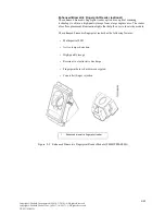
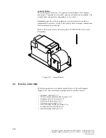
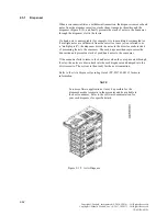
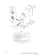
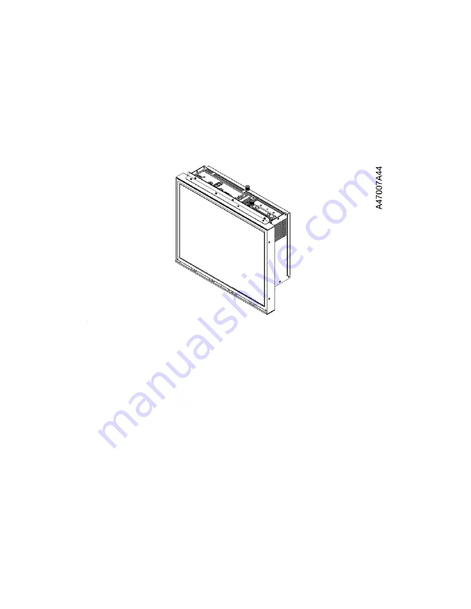
For the Diebold Nixdorf CS 5550 through-the-wall cash dispenser, the processor
module is attached to the consumer display which is assembled to the all in one
module (Figure 2-15).

The operator uses the consumer display for routine maintenance, balancing
transaction reports, replenishing supplies and monitoring maintenance services.
A green or red indicator on the display signi

fi

es the following status:

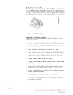
When the main power switch is turned on, the display has power. If the display is
not on, double-check the main power (on/off) button on the switch bracket inside
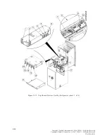
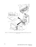
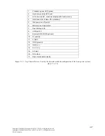
of the upper cabinet (Figure 2-12) in the back and make sure the button is on.

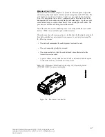
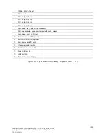
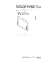
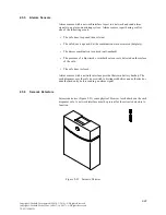
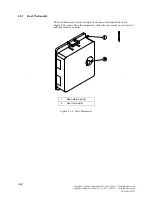
Figure 2-15 ActivCore Processor Module-Consumer Display

2-19

Copyright ©Diebold, Incorporated (9/2014, 3/2016) - All Rights Reserved
Copyright ©Diebold Nixdorf, Inc. (4/2017, 10/2017) - All Rights Reserved
TP-821765-001D

Summary of Contents for CS 5550

Page 1: ...Diebold Nixdorf CS 5550 Through the Wall Cash Dispenser Operating Guide TP 821765 001D PD 7332 October 2017...

Page 2: ...of the copyright owner are prohibited This document should be treated as confidential material for security reasons Any unauthorized disclosure or use of confidential material may violate Section 1832...

Page 3: ...3 4 3 3 1 Opening the Mechanical Combination Locks LaGard 3390EX 3 7 3 3 2 Opening the ComboGard 6040 Electronic Lock 3 7 3 3 3 Opening the Cencon System 2000 GEN 2 Electronic Lock 3 8 3 3 4 Opening t...

Page 4: ...2 24 Figure 2 20 Divert Retract Cassette and Divert Bin 2 25 Figure 2 21 ActivDispense Cassettes 2 26 Figure 2 22 Safe Door Locks 2 28 Figure 2 23 Seismic Detector 2 29 Figure 2 24 Heat Thermostat 2...

Page 5: ...vice procedures are performed from the back of the system 1 1 Before Performing Maintenance Procedures on the Cash Dispenser The operator should be familiar with the following information before perfo...

Page 6: ...ional on a day to day basis and includes but is not limited to the following tasks Retrieving jammed retained or captured cards from the card reader Replenishing printer paper clearing paper jams and...

Page 7: ...ent damage Do not wear loose clothing or jewelry that can become caught in the equipment Use caution to prevent long hair from getting caught in the equipment Never insert screwdrivers pens or other i...

Page 8: ...mperature hazard or refer to the module or ATM operating guide for the specific hazard Pinch point An area that can pinch or cut you exists in the area of this label Keep your hands and fingers clear...

Page 9: ...efers to documents of monetary value that are stored in the cassettes and dispensed from the dispenser Consumer refers to any person who uses the cash dispenser to conduct transactions Device refers t...

Page 10: ...enser Module refers to the major electro mechanical devices that are installed in the cash dispenser such as displays printers and dispensers Operator refers to a person who performs routine maintenan...

Page 11: ...rroundings while they use the cash dispenser Camera Window The fascia contains windows for an optional camera for the cash pocket and an optional camera security system Motorized Card Reader Slot To u...

Page 12: ...ing PIN pad technology to secure the transaction information Function Keypads The consumer can use the four function keys on each side of the consumer display to make selections on the consumer displa...

Page 13: ...era 14 Dispenser slot 6 ActivCore processor consumer display 15 Printer slot 7 Function keys 16 2D bar code scanner 8 Headphone jack 17 Consumer keypad 9 Motorized card reader slot 18 Contactless card...

Page 14: ...r Receipt printer 1 Lead through indicator example 2 Dip card reader lead through indicator 3 Motorized card reader lead through indicator 4 Active edge card reader indicator 5 Dispenser lead through...

Page 15: ...or dip card reader or active edge card reader Graphical receipt printer 2D Barcode scanner optional Fingerprint reader optional Enhanced biometric fingerprint reader optional Contactless card reader o...

Page 16: ...ader 6 Enhanced biometric fingerprint reader optional 7 Fingerprint reader optional 8 2D Barcode Scanner 9 Contactless card reader optional Figure 2 3 Consumer Devices in the Top Chassis 2 6 Copyright...

Page 17: ...86 is an available option with the reader The card reader has either an open bin or a locked bin to hold retained cards both bins hold cards that are not returned to consumers A card may be retained f...

Page 18: ...or retain cards Refer to the Dip Card Reader with chip 123 Operating Guide TP 820814 001C for more information Figure 2 5 Dip Card Reader ActiveEdge Card Reader optional An optional ActiveEdge card re...

Page 19: ...inches in diameter The receipt printer has a minimum length of 3 inches and a maximum length of 6 inches the length of the receipt can be programmed according to the needs of the institution Black ma...

Page 20: ...hat help the user to locate the module The fingerprint reader has the following features Blue LED High quality image Resistant to electrostatic discharge Fingerprint data is encrypted Counterfeit fing...

Page 21: ...nced biometric fingerprint reader has the following features Multispectral LED Active tamper detection High quality image Resistant to electrostatic discharge Fingerprint data is hardware encrypted Co...

Page 22: ...less smart cards Ability to drive any type of MIFARE contactless smart cards Ability to drive any type of ISO7816 contact smart card or SIM SAM card Support for smart card with a higher baud rate cont...

Page 23: ...perform routine operations such as setting up the system balancing transaction reports replenishing supplies and diagnosing problems Rear operator display All in one module the consumer display USB p...

Page 24: ...12 Top Chassis Devices Used by the Operator sheet 1 of 2 2 14 Copyright Diebold Incorporated 9 2014 3 2016 All Rights Reserved Copyright Diebold Nixdorf Inc 4 2017 10 2017 All Rights Reserved TP 8217...

Page 25: ...vity LED red 10 Processor power LED green 11 External DVD ROM optional 12 Main power on off switch 13 Idle power on off switch 14 Maintenance mode switch 15 Dual USB port 2 0 16 USB port 2 0 17 Rear m...

Page 26: ...Used by the Operator with the configuration of the basic power system sheet 1 of 2 2 16 Copyright Diebold Incorporated 9 2014 3 2016 All Rights Reserved Copyright Diebold Nixdorf Inc 4 2017 10 2017 Al...

Page 27: ...2 0 8 USB port 2 0 9 External DVD ROM optional 10 N neutral 11 L light 12 GND ground 13 GND V 14 24 V V 15 AC inlet 16 DC output 17 Rear maintenance display Figure 2 13 Top Chassis Devices Used by th...

Page 28: ...nce procedures on the rear display it could be rotated reversely for service after opening the rear door The display LED also provides status information about the cash dispenser with the following th...

Page 29: ...onitoring maintenance services A green or red indicator on the display signifies the following status When the main power switch is turned on the display has power If the display is not on double chec...

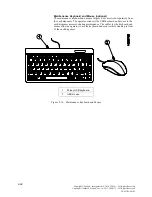
Page 30: ...spenser processor during maintenance The cables for the keyboard and mouse allow an operator to use the keyboard and mouse while standing in front of the cash dispenser 1 85 key USB keyboard 2 USB mou...

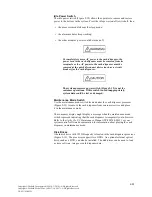
Page 31: ...ntenance mode switch located under the cash dispenser processor Figure 2 12 to remove the cash dispenser from consumer service and place it in the maintenance mode The consumer display might display a...

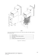
Page 32: ...uide TP 820817 001A for more information Figure 2 17 Journal Printer 2 3 Devices in the Safe The following devices are installed inside the safe of the cash dispenser Figure 2 18 Your cash dispenser m...

Page 33: ...mostat are not shown 1 Safe door locks 2 Secondary mechanical keylock optional 3 Safe handle 4 Dispenser with divert and dispense cassettes Figure 2 18 Safe Devices 2 23 Copyright Diebold Incorporated...

Page 34: ...processes the transaction and presents a stack of good bank notes to the consumer If the consumer fails to remove the bank notes when they are presented through the slot the notes are drawn back into...

Page 35: ...lastic bin with the following characteristics can be used in the dispenser instead of the divert cassette Customer contact points on the cassette are blue Available without a lid a lock or security fe...

Page 36: ...0 mm 13 inches deep Dispense cassettes Figure 2 21 are available with no lock convenience cassette or with standard locks tamper indicating cassette Refer to the ActivDispense Operating Guide TP 82176...

Page 37: ...ck Cencon SafeGard and S G electronic locks are available with such features as single combination dual combination remote access combination etc Refer to Section 3 3 and Section 3 4 for information a...

Page 38: ...ical combination lock 3 Single dual electronic lock 4 OTC electronic lock 5 Keylock Class B 6 Keylock UL 437 secondary keylock optional Figure 2 22 Safe Door Locks 2 28 Copyright Diebold Incorporated...

Page 39: ...rface of the safe The safe door is closed Alarm sensors with a network interface provide their own battery backup The cash dispenser uses the safe door switch to distinguish between an authorized or u...

Page 40: ...ses when the temperature inside the safe exceeds a certain level and then initiates an alarm 1 Basic alarms panel 2 Heat thermostat Figure 2 24 Heat Thermostat 2 30 Copyright Diebold Incorporated 9 20...

Page 41: ...tion 3 5 Accessing Cash Dispenser Components and Modules To avoid risk of death severe personal injury or equipment damage always follow the written maintenance procedures for the cash dispenser and i...

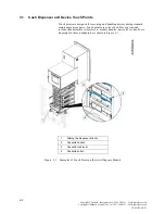
Page 42: ...release levers module handles device levers knobs etc Examples of these touchpoints are shown in Figure 3 1 1 Sliding the dispenser directly 2 Cassette handle 3 Cassette lock lever 4 Cassette button...

Page 43: ...he documentation for the system control software to place the cash dispenser in maintenance mode 5 Refer to the appropriate operating guide listed in Appendix A for information about completing the ma...

Page 44: ...291 24 hour Service Level 1 burglary resistance protection The mechanical keylock does NOT provide burglary resistance protection 1 Mechanical combination lock LaGard 3390EX 2 Keylocking feature 3 Key...

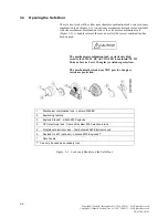
Page 45: ...r locks Safe Handle The safe handle releases the door after it is unlocked General Procedure to Open the Safe Door 1 Pay attention to the following recommended sequence when opening the safe installed...

Page 46: ...ing handle clockwise 2 Open the safe door Figure 3 4 Open the Safe Door 3 6 Copyright Diebold Incorporated 9 2014 3 2016 All Rights Reserved Copyright Diebold Nixdorf Inc 4 2017 10 2017 All Rights Res...

Page 47: ...d dial the combination 3 Turn the dial clockwise until it stops Figure 3 5 Opening the Mechanical Combination Lock 3 3 2 Opening the ComboGard 6040 Electronic Lock Perform the procedure to enter the l...

Page 48: ...handle clockwise until it stops 1 Spin the dial left counterclockwise until the letters EC appear on the display see Figure 3 6 2 Enter the lock combination on the electronic lock keypad refer to the...

Page 49: ...s see Figure 3 7 4 The lock is now unlocked 1 Turn the dial clockwise until it stops 2 The letters OPr appear on the display Figure 3 7 Operating the Cencon System 2000 GEN 2 Lock 3 9 Copyright Diebol...

Page 50: ...the S G 6880 Keylock 3 3 5 Opening the Lagard 2270 Keylocks Insert the key into the keylock and turn it clockwise to open the keylock Figure 3 9 1 Insert the key into the keylock and turn it clockwis...

Page 51: ...counterclockwise until it stops Figure 3 10 Closing the Safe Door 3 Close the primary lock choose the appropriate procedures from Section 3 4 1 to Section 3 4 5 4 Close the secondary lock choose the...

Page 52: ...p at 0 2 Insert the key and turn it counterclockwise 3 Remove the key from the dial Figure 3 11 Closing the Mechanical Combination Lock 3 4 2 Closing the ComboGard 6040 Electronic Lock The ComboGard 6...

Page 53: ...n 2000 GEN 2 Electronic Lock 3 4 4 Closing the S G 6880 Keylocks Insert the key into the keylock and turn it counterclockwise to close the keylock Figure 3 13 1 Insert the key into the keylock and tur...

Page 54: ...n describes the procedures to access the various modules and components in the cash dispenser 3 5 1 Accessing the Dispenser 1 Open the safe door following Section 3 3 2 The front of the dispenser and...

Page 55: ...nser maintenance is complete push the dispenser completely into the cash dispenser and make sure that the plunger for the dispenser slide assemblies latches securely 6 Close the cash dispenser safe do...

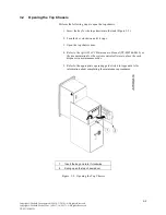
Page 56: ...pull the slide handle to slide the card reader receipt printer or journal printer out of the cabinet for maintenance Figure 3 16 4 Open the upper fascia to access the processor the cash dispenser pro...

Page 57: ...ckwise to open the rear door 6 Top chassis tray handle 7 Plunger Figure 3 16 Accessing the Motorized Card Reader the Receipt Printer and the Processor 3 17 Copyright Diebold Incorporated 9 2014 3 2016...

Page 58: ...perating Guide TP 820814 001C Consumer Bar Code Scanner Operating Guide TP 820813 001A Journal Printer Operating Guide TP 820817 001A SafeGard Electronic Lock Customer Operating Instructions TP 820466...

Page 59: ...mpounds DO NOT use abrasive scouring pads such as steel wool Scotch Brite and so forth DO NOT use high pressure cleaning systems such as power washers On systems not rated for weather exposure use cau...

Page 60: ...tor to keep the cash dispenser operational such as replenishing supplies Media A generic term that refers to any type of document such as a bank note ticket coupon etc that is stored in the cassettes...

Reviews: