background image

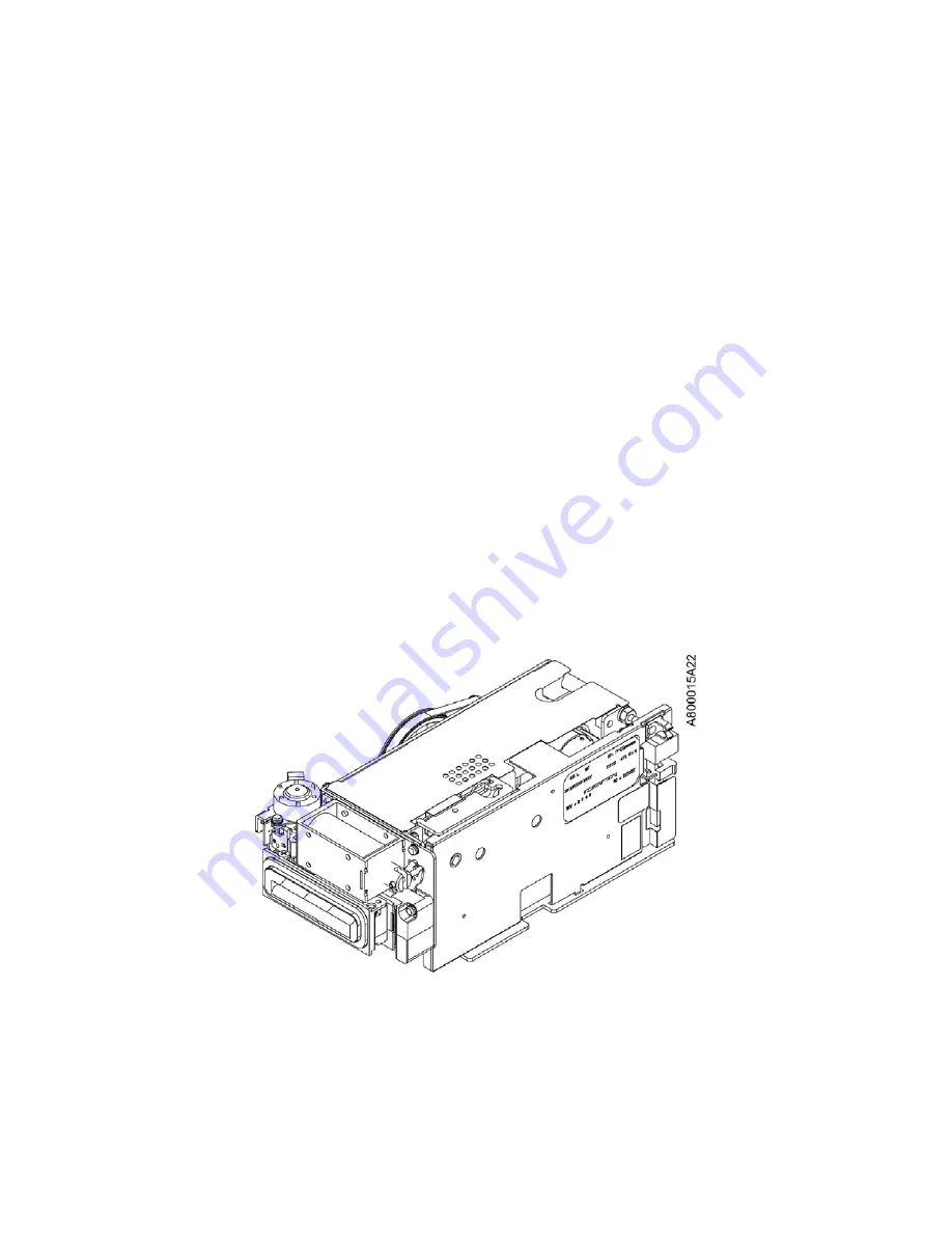
Motorized Card Reader

Consumers insert their card into the motorized card reader slot to begin the
transaction. A blinking lead-through indicator light surrounds the slot to help
guide the consumer.

The motorized card reader reads and writes magnetic stripe cards and memory
chip cards (smart or memory cards compliant with ISO 7816) . The card reader
reads and writes tracks 1, 2, and 3 (or any combination of tracks 1, 2, and 3)
of magnetic stripe cards. To minimize errors, the card is held in the transport
and the card reader can read tracks with errors again, for corrections (when it is
necessary). A gate prevents cards without chips or cards without track 2 from
entering the card reader/writer. The gate also prevents incorrect card insertion.

The card reader has an open card capture box to hold retained cards. The card
capture box holds all cards that are not returned to consumers. A card may be
retained for the following reasons:

• The network commands the system to retain the card.

• The card cannot physically be returned.

• The consumer fails to take the card within the time allowed after the

transaction session ended.

• A power failure occurs while the card is in the card reader, and the option to

return the card during power failure is not enabled.

Refer to the

Motorized Card Reader (with chip, 123) Operating Guide

(TP-820815-001C).

Figure 2-9 Motorized Card Reader

2-9

Copyright ©Diebold, Incorporated (7/2015) - All Rights Reserved
Copyright ©Diebold Nixdorf, Inc. (4/2017, 9/2018) - All Rights Reserved
TP-821815-001C

Summary of Contents for CS 7790

Page 1: ...Diebold Nixdorf CS 7790 Island Drive up System Operating Guide TP 821815 001C PD 7522 September 2018...

Page 2: ...rized disclosure or use of con dential material may violate Section 1832 of Title 18 of the United States Code as well as other laws and may be punishable by ne and imprisonment The information contai...

Page 3: ...3 1 1 Cold Start Condition 3 3 3 1 2 Recovery and Warm up 3 3 3 1 3 Guidelines to Minimize Environmental Exposure 3 5 3 2 Switching the System to Maintenance Mode 3 5 3 3 Accessing the Upper Chassis 3...

Page 4: ...2 21 Figure 2 20 ActivCash Dispenser 2 23 Figure 2 21 ActivCash Dispenser 2 24 Figure 2 22 Divert Cassette Types 2 25 Figure 2 23 ActivCash Dispense Cassettes 2 27 Figure 2 24 ActivMedia Cassette Unit...

Page 5: ...ble 2 2 Media Capacity of the Dispense Cassette 2 26 Table 2 3 Media Parameters 2 29 Table 3 1 System Exposure and Recovery Times 3 4 Table A 1 Hardware Documentation A 1 v Copyright Diebold Incorpora...

Page 6: ...s transaction records to consumers It is recommended to have a form of enclosure for the system to protect its components from exposure to rain or snow during servicing Supplies are replenished and se...

Page 7: ...e tasks include the following Retrieving jammed retained or captured cards from the card reader Replenishing printer paper clearing paper jams and replacing printer cartridges Removing jammed media fr...

Page 8: ...l injury or death can be reduced Do not wear loose clothing or jewelry that can be caught in the equipment Use caution to prevent long hair from getting caught in the equipment Never insert screwdrive...

Page 9: ...re hazard or refer to the module or system operating guide for the speci c hazard Pinch point An area that can pinch or cut you exists in the area of this label Keep your hands and ngers clear of pinc...

Page 10: ...the consumer ActivMedia depositor refers to the device that accepts media checks or currency from the consumer through a slot in the fascia and deposits the media in a cassette ATM is used interchang...

Page 11: ...An operator may also perform procedures that help determine the cause of certain problems such as jammed paper in the printer Safe refers to the high security enclosure below the upper chassis Devices...

Page 12: ...reader X X Fascia Dip card reader X Fascia ActivEdge card reader X X Fascia Encrypting PIN pad consumer keypad X Fascia Headphone jack X Fascia ActivCash dispenser X X Safe Coin dispenser X X Upper c...

Page 13: ...electing transactions Specifying amounts Receiving currency or other dispensable media and receipts Depositing media currency and checks Requesting information Inserting and retrieving passbooks The d...

Page 14: ...Headphone jack 17 ActivCash dispenser 7 Receipt printer 18 Function keys 15 inch consumer display 8 Encrypting PIN pad consumer keypad 19 Consumer display 9 Card reader 20 Speakers 10 Dip card reader...

Page 15: ...tracking and routing purposes The barcode reader is commanded by the system control software and can decode both one dimensional and two dimensional barcodes The consumer uses the barcode reader by r...

Page 16: ...ncing and monitoring supplies and service tasks Consumer Display with Function Keypad The 15 inch consumer display see Figure 2 3 welcomes the consumer and provides instructions for performing transac...

Page 17: ...umer Keypad Lead through Indicators Lights guide the consumer through a transaction by calling attention to the next step in the transaction These bar shaped indicators can display in colors and are u...

Page 18: ...ActivEdge card reader 5 ActivMedia depositor 6 Coin dispenser 7 ActivCash dispenser Figure 2 5 Lead through Indicators 2 6 Copyright Diebold Incorporated 7 2015 All Rights Reserved Copyright Diebold...

Page 19: ...bank card format Figure 2 6 Identi cation Card Scanner ActivEdge Card Reader The ActivEdge card reader reads data from magnetic cards IC cards and smart EMV chip cards when the card is inserted long...

Page 20: ...transaction The dip card reader can read magnetic stripe cards and chip cards The dip card reader cannot retract capture or retain cards Refer to the Dip Card Reader with chip 123 Operating Guide TP 8...

Page 21: ...2 from entering the card reader writer The gate also prevents incorrect card insertion The card reader has an open card capture box to hold retained cards The card capture box holds all cards that ar...

Page 22: ...front of the reader to initiate the transaction The card reader beeps and LEDs illuminate brie y to indicate that the card has been read successfully Figure 2 10 Contactless Card Reader Receipt Print...

Page 23: ...n this section Some devices are optional and some devices cannot be used in combination with other devices mutually exclusive combinations 1 Coin dispenser 4 ActivMedia head unit 2 Receipt printer 5 M...

Page 24: ...e assembly containing currency or media between the ActivCash dispenser and the system fascia 1 ActivCash shuttle tracks 2 Convenience divert retract cassette 3 Convenience cassette Figure 2 12 ActivC...

Page 25: ...or bank notes individually or as a bundle A bundle may contain a mixture of checks and bank notes and can consist of up to 75 checks or bank notes Refer to ActivMedia Mixed Media Acceptor Operating G...

Page 26: ...es coins in four different denominations See Figure 2 14 1 Upper main tray 2 Coin dispenser 3 System Figure 2 14 Coin Dispenser 2 14 Copyright Diebold Incorporated 7 2015 All Rights Reserved Copyright...

Page 27: ...cs in two colors Depending on the software application the journal printer can also be programmed to provide a variety of data such as status messages service actions maintenance actions commands and...

Page 28: ...ansfers the system number and location and other desired information The receipt printer uses rolled paper 80 mm 3 15 in wide The paper may have optional top of form marks The length is also programma...

Page 29: ...pen the upper chassis Unauthorized access can be detected and reported to customer applications and security monitoring services Managing authorized users is on a per system basis and can be managed s...

Page 30: ...es see Figure 2 18 1 Upper Control Card 5 Idle switch 2 Location of Upper Control Card in the system 6 Maintenance switch 3 Fascia 7 USB power ports service 4 Power switch 8 USB ports Figure 2 18 Uppe...

Page 31: ...to turn OFF the system including hubs It may take several minutes for the system to completely turn off When the system does turn off the ON OFF LED will then turn off To completely remove AC power to...

Page 32: ...ash dispense cassettes Section 2 3 3 ActivMedia cassette unit Section 2 3 4 ActivMedia retract cassette Section 2 3 5 ActivMedia deposit cassettes Section 2 3 6 Safe lock Section 2 3 7 System switches...

Page 33: ...mostat are not shown 1 System 2 Safe door cover 3 Safe door 4 ActivMedia cassette unit 5 ActivCash dispenser Figure 2 19 Devices Located in the Safe 2 21 Copyright Diebold Incorporated 7 2015 All Righ...

Page 34: ...tilated or crumpled to dispense or if multiple bills are picked in place of one bill the ActivCash dispenser diverts the bill s to the divert cassette If the consumer fails to remove the stack of medi...

Page 35: ...enience divert retract cassette 3 Convenience cassette Figure 2 20 ActivCash Dispenser 2 23 Copyright Diebold Incorporated 7 2015 All Rights Reserved Copyright Diebold Nixdorf Inc 4 2017 9 2018 All Ri...

Page 36: ...Figure 2 21 ActivCash Dispenser 2 24 Copyright Diebold Incorporated 7 2015 All Rights Reserved Copyright Diebold Nixdorf Inc 4 2017 9 2018 All Rights Reserved TP 821815 001C...

Page 37: ...cure cassette with a lock or a convenience cassette without a lock Refer to the ActivCash Dispenser Operating Guide TP 821707 001B for more information 1 Convenience divert retract cassette 2 Secure d...

Page 38: ...imum Size of low media stack Con gurable trip points 500 maximum 400 300 200 100 50 25 minimum notes Capacity US and Euro 432 mm total capacity approximately 3750 notes NOTE Media that is not new but...

Page 39: ...e 3 Dispense cassette key 4 Dispense cassette lock lever Figure 2 23 ActivCash Dispense Cassettes 2 27 Copyright Diebold Incorporated 7 2015 All Rights Reserved Copyright Diebold Nixdorf Inc 4 2017 9...

Page 40: ...eit documents and checks or bank notes that are returned to the input output tray but not removed by the customer Refer to ActivMedia Mixed Media Acceptor Operating Guide TP 821683 001B for more infor...

Page 41: ...ain media that meet the size limitations shown in Table 2 3 Table 2 3 Media Parameters Bank Note Checks Length 120 to 190 mm 4 72 to 7 48 inches 140 to 240 mm 5 51 to 9 45 inches Width 60 to 99 mm 2 3...

Page 42: ...y with lock for check deposit cassette 4 Key with lock for cash deposit cassette Figure 2 26 Deposit Cassettes 2 30 Copyright Diebold Incorporated 7 2015 All Rights Reserved Copyright Diebold Nixdorf...

Page 43: ...alarm monitoring system Alarm sensors report during or after one of the following events The door of the safe is opened or closed door status The door of the safe is opened but the combination was no...

Page 44: ...own alarm systems within the safe An area within the safe is designated for third party alarm installation 2 3 12 Heat Thermostat The heat thermostat integral to the basic alarms panel senses when the...

Page 45: ...closing mechanical combination locks Section 3 7 Before proceeding be sure you have the upper chassis door key the safe door cover key and the correct lock combination To avoid risk of death severe p...

Page 46: ...kept to a minimum Cold temperature exposure is extremely critical Refer to the Opteva 750 ATM Operating Guide TP 820918 001E for more information If the system is opened and exposed directly to rain...

Page 47: ...warm up period 4 After the required minimum warm up period open the upper chassis 5 Press and release the system power button to turn on the system After the system has completely powered up the termi...

Page 48: ...to place the system in service Table 3 1 System Exposure and Recovery Times Outside Temperature Range Description Maximum Exposure and Recovery Times 5 to 1 C Maximum exposure any upper chassis or do...

Page 49: ...3 3 1 Opening the Upper Chassis Perform the following steps to open the fascia and access the upper chassis modules 1 Insert the key into the fascia access door key slot See Figure 3 1 2 Turn the key...

Page 50: ...xed grip latch rotate 90 degrees counterclockwise to open 6 Fascia access door 7 Fascia access door key slot turn the key clockwise to open Figure 3 1 Opening the Fascia and Access Door 3 6 Copyright...

Page 51: ...fascia assembly away from the system to make sure that both fascia latches are securely locked and in place 3 If necessary insert the key into the fascia key slot and turn the key counterclockwise to...

Page 52: ...ey counterclockwise to close 3 Fascia in extended position Figure 3 2 Closing the Fascia 3 8 Copyright Diebold Incorporated 7 2015 All Rights Reserved Copyright Diebold Nixdorf Inc 4 2017 9 2018 All R...

Page 53: ...bly release levers module handles device levers knobs etc See Figure 3 3 for an example of the upper chassis touch points 1 Coin dispenser tray handle 2 Printer tray handle 3 Printer tray release leve...

Page 54: ...latch and extend the ActivMedia head unit on its slide assemblies see Figure 3 4 4 Refer to the ActivMedia Mixed Media Acceptor Operating Guide TP 821683 001A for speci c maintenance procedures 5 Pus...

Page 55: ...lease latch 3 ActivMedia head unit 4 Upper chassis 5 ActivMedia head unit slider Figure 3 4 Accessing the ActivMedia Head Unit 3 11 Copyright Diebold Incorporated 7 2015 All Rights Reserved Copyright...

Page 56: ...it to service position see Figure 3 5 The coin dispenser tray is now accessible 4 Perform the necessary maintenance activity Refer to the module operating guide listed in Appendix A for speci c mainte...

Page 57: ...er tray 4 Coin dispenser tray handle 5 Coin dispenser release lever Figure 3 5 Accessing the Coin Dispenser 3 13 Copyright Diebold Incorporated 7 2015 All Rights Reserved Copyright Diebold Nixdorf Inc...

Page 58: ...afe door cover and various safe lock types refer to Section 3 5 3 4 1 Safe Touch Points See Figure 3 6 for an example of the safe touch points 3 14 Copyright Diebold Incorporated 7 2015 All Rights Res...

Page 59: ...ia cassette unit handle 4 ActivCash dispenser handle 5 ActivCash dispenser release latch Figure 3 6 Safe Touch Points 3 15 Copyright Diebold Incorporated 7 2015 All Rights Reserved Copyright Diebold N...

Page 60: ...its slide assemblies see Figure 3 7 3 Refer to the ActivCash Dispenser Operating Guide TP 821707 001B for speci c maintenance procedures 4 Push the ActivCash dispenser completely into the safe until i...

Page 61: ...er in extended position 6 ActivCash dispenser slider quantity 2 7 ActivCash dispenser release latch Figure 3 7 Accessing the ActivCash Dispenser 3 17 Copyright Diebold Incorporated 7 2015 All Rights R...

Page 62: ...it on its slide assemblies see Figure 3 8 3 Refer to the ActivMedia Mixed Media Acceptor Operating Guide TP 821683 001B for speci c maintenance procedures 4 Push the ActivMedia cassette unit completel...

Page 63: ...over 4 Safe door 5 ActivMedia cassette unit in extended position Figure 3 8 Accessing the ActivMedia Cassette Unit 3 19 Copyright Diebold Incorporated 7 2015 All Rights Reserved Copyright Diebold Nixd...

Page 64: ...ns of the available safe locks and handles 3 5 1 Opening the Safe Door Cover Perform the following steps to unlock and open the safe door cover 1 Insert the key into the key slot on the safe door cove...

Page 65: ...kwise direction 4 Safe door cover 5 Fixed grip latches Figure 3 9 Opening the Safe Door Cover 3 Reverse Step 1 and Step 2 to close the safe door cover 3 21 Copyright Diebold Incorporated 7 2015 All Ri...

Page 66: ...sed to release the door See Figure 3 10 for illustrations of the available safe locks and handles 1 Electronic combination lock 2 Mechanical combination lock with mechanical keylock 3 Cencon 2000 GEN...

Page 67: ...dial When the code is successfully entered the lock dial is turned to the right to release the lock bolt Then the handle can be turned to open the safe Safe Opening Handle The safe opening handle rel...

Page 68: ...p latches counterclockwise 90 degrees and open the safe door cover 3 Enter the combination of the lock through the lock keypad to unlock the lock bolt refer to the appropriate lock operating guide lis...

Page 69: ...ion 3 Direction to turn dial clockwise 4 Display Figure 3 11 Opening Electronic Combination Locks 3 25 Copyright Diebold Incorporated 7 2015 All Rights Reserved Copyright Diebold Nixdorf Inc 4 2017 9...

Page 70: ...reaches the closed position the handle turns automatically in the closed position 2 Remove the key from the lock 3 Make sure that the handle of the safe does not turn 4 Pull rmly on the door of the sa...

Page 71: ...ck 4 Direction to turn dial counterclockwise 5 Display 6 Factory set combination Figure 3 12 Closing Electronic Combination Locks 3 27 Copyright Diebold Incorporated 7 2015 All Rights Reserved Copyrig...

Page 72: ...a keylock for the mechanical combination lock insert the key into the lock and turn the key clockwise until it stops 4 Dial the combination selected for the system 5 Turn the dial clockwise until it...

Page 73: ...the combination 4 Turn the dial clockwise until it stops 5 Turn the handle of the safe clockwise until it stops 6 Open the safe door Figure 3 13 Opening Mechanical Combination Locks 3 29 Copyright Di...

Page 74: ...e combination This action closes the lock bolt to lock the door shut 3 If there is a keylock for the mechanical combination lock insert the key into the lock and turn the key counterclockwise until it...

Page 75: ...e three revolutions and stop at 0 4 Insert the key into the lock and turn it counterclockwise 5 Remove the key from the dial Figure 3 14 Closing Mechanical Combination Locks 3 31 Copyright Diebold Inc...

Page 76: ...perating Guide TP 820817 001A Motorized Card Reader with chip 123 Operating Guide TP 820815 001C ActivEdge Secure Card Reader Operating Guide TP 821629 001A Contactless Card Reader CCR2e CCR2 Operatin...

Page 77: ...T use abrasive cleaning compounds DO NOT use abrasive scouring pads such as steel wool Scotch Brite or similar materials DO NOT use high pressure cleaning systems such as power washers On systems not...

Reviews: