Installation Guide
V 1.8 13 / 64
Installation steps
1) Check the place of installation:
The environmental condition has to be protected from direct sun rays, heat, humidity, impurity and
vibration as well as sufficient distance to sources of electromagnetic interference.
Due to its construction the calculator is well protected against electromagnetic interferences.
Nevertheless it has to be made sure that the distance between the meter (calculator, flow-sensor,
temperature-sensors and their cables) and possible sources of electromagnetic interference
(frequency-controlled devices: converters and pumps or switches, electric motors, fluorescent
lamps, etc.) is sufficient.
The calculator must be installed on the wall at a sufficient distance from heat sources. The meter
should be installed in a convenient position for service and operating personnel.
2) Check of the components:
Before starting up the measurement the compatibility of the calculator with the flow sensors in use
(pulse-value and location of flow sensor) and their respective temperature sensors (PT100 or
PT500) have to be ensured.
Compare the calculator settings with the flow sensors pulse-value and the location of the flow
sensors in use.
Depending on the programming of the calculator the flow sensor is either mounted in the hot line
or in the cold line. You will find which place of installation the calculator is programmed for in the
menu
“Unit Info”
under
“Pulse Input A”
or
"Pulse
Input B”.
The adjusted pulse values can be compared with the relevant flow sensors in the same menu.
Compare the calculator settings with the temperature sensors in use (PT100 or PT500).
It is possible to connect PT100 or PT500 temperature sensors at the energy-calculator.
You will find which type of temperature sensor (PT100 or PT500) the calculator is programmed
for in the menu
“Unit Info”
under
“PT 100/500”.
This information might also be read out on an additional sticker on the front side of the calculator.
Due to its construction the calculator is especially well protected against electromagnetic
interference.
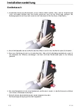
3) Install the calculator on a solid wall by using the mounting panel or on the enclosed DIN-rail (top-hat
rail). For this purpose two connecting clips are fixed on the back of the calculator. These clips first
must be attached to the upper side of the rail and then the calculator is pressed completely into the
rail.
4) Open the calculator and remove the transport lock (if any). It must not be re-inserted during the
operation.
5) Insert the connection cables via the cable glands.The cable entry is done via cable gland.
Depending on the type there are up to 6pcs. PG11 and 6 pcs. PG7 available.
The cable lengths inside the device are to be chosen in a way that the calculator can easily be
opened and closed. The cable glands have to be sufficiently fixed so that tensile strain on the
clamps is avoided.
6) Clamp the in- and output cables to the connectors.
7) Clamp the power supply cables to the connectors.
8) Close the calculator and check the meter for correct operation by pressing the buttons and
controlling the momentary values. If necessary seal the calculator.
9) In case outputs or AUX inputs are used, they can now be adjusted.


