Installation Guide
V 1.8 33 / 64
Optional interfaces
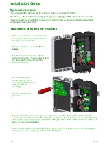
The heat calculator has four slots for extension modules, e.g. for a 2
nd
M-Bus.
Attention:
The modules may only be plugged or unplugged if the power is switched off.
These modules have no effect on consumption recording and can be retrospectively fitted without
damaging the calibration mark.
Installation of extension modules
1.)
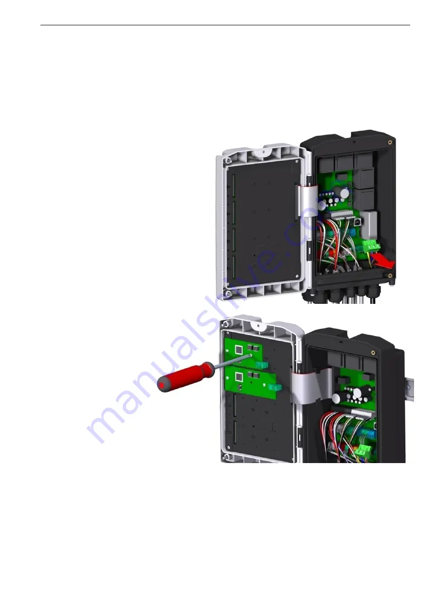
Open the calculator. In case there is a
seal, remove the seal from the calculator
housing and open the lid.
2.)
The calculator is to be made
free of
power.
3.)
The heat calculator has four slots for
extension modules. They are placed inside
the upper part (on the left side if the
calculator is open).
4.)
The module is to be
carefully plugged in an
unused plug and screwed
to the predefined
mountings.
5.)
The calculator is to be
powered.
6.)
The communication cable can only be inserted via a free cable gland and be connected to the
extension module The cable lengths inside the device are to be chosen in a way that the calculator
can easily be opened and closed. Finally the cable glands have to be sufficiently fixed so that tensile
strain on the clamps is avoided
7.)
Close the lid and check the meter for correct operation by pressing the buttons and controlling the
momentary values. If necessary seal the calculator again.


