ENGLISH
- 13 -
Each probe type PT100 is gifted with three wires, one of them is white and the other
two are red.
Connect the white wire to the terminal board marked whit sensor logo on plugs (3-6-9-
12-15-18-21-24).
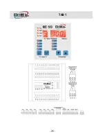
The twenty-four connectors relevant to the eight probes are divided as follows:
Probe N. 1 connectors 1-2-3, Probe N. 2 connectors 4-5-6.
Probe N. 3 connectors 7-8-9, Probe N. 4 connectors 10-11-12.
Probe N. 5 connectors 13-14-15, Probe N. 6 connectors 16-17-18.
Probe N. 7 connectors 19-20-21, Probe N. 8 connectors 22-23-24.
Serial communication interface RS485 full duplex.
•
Transmission positive TX+: connector 25.
•
Transmission negative TX-: connector 26.
•
Receive positive RX+: connector 28.
•
Receive negative RX-: connector 27.
All measured signals cables must preferably be:
•
Separated from the power cables
•
Screened better even if twisted
•
With a section of not less than 0.5 mm
2
MESSAGES DESCRIPTION
The letters that appear on single digit display assume the following meaning:
F: function mode (range 0-3)
P: pre alarm level, the PrE relay switch on when the temperature exceeds the level set
A: alarm level, the ALL relay switch on when the temperature exceeds the level set
L: low level for cooling system switch off, the AIr relay switch off when the temperature
gets lower than all L values
H: High level for cooling system switch on, the AIr relay switch on when the
temperature gets higher than any H value
t: min. time that must elapse before the device turn off the fan cooling system (see
programming details for more information)
S: RS485 speed (see details to chapter PROGRAMMING)
d: answer delay on RS485 serial communication interface in hundredths second (see
details to chapter PROGRAMMING)
U: Address of device on RS485 network
Summary of Contents for ME 100 V3
Page 2: ......
Page 26: ...TAB 1 26 ...


