Dietz-motoren GmbH & Co. KG
Eisenbahnstrasse 67 73265 Dettingen/Teck
Tel.: +49 7021 57 02-0
Fax: +49 7021 57 02-14
www.dietz-motoren.de vertrieb@dietz-motoren.de
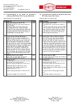
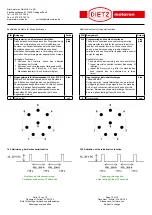
16.4 Anschlussbelegung für den Betrieb der Nachschmier-
einrichtung mittels Stecker M12x1; 8-poliger Kabelbuchse
Standardkontakte für den Normalbetrieb
PIN Belegung
Farbe
1
Eingangssp14 bis +30 VDC
Die Spannung an PIN 1 wird nur zum Schalten der
Einheit benötigt!
Die Stromaufnahme aus der angeschlossenen
Spannungsquelle ist damit sehr gering (typisch
<15mA). Der Stromverbrauch hängt im Wesentlichen
vom Strom des angeschlossenen Verbrauchers am
Ausgang des PIN 2 bzw. PIN 4 ab. Der Eingang ist
kurzschlussfest und verpolungssicher.
weiß
2
Ausgangssignal, Motorlauf-Bestätigung
Zeitgleich mit dem Motorlauf des Antriebsmotors
(Spendevorgang) wird auf dem PIN 2 für exakt zehn
Sekunden ein High-Signal geschaltet. Dieses Signal
kann beispielsweise zur Bestätigung der erfolgten
Spende und/oder zum Zählen der bereits absolvierten
Spendezyklen genutzt werden. Der Ausgang auf PIN 2
ist mit maximal 200 mA belastbar und kurzschlussfest.
Zwischen den einzelnen Spendezyklen liegt auf
diesem PIN ein Low-Signal an. Unmittelbar beim
Anlegen des Signals auf PIN 1, erfolgt auf PIN 2 ein
kurzer Peak für ca. 7 ms. Bei einer Motorlaufabfrage
durch die Maschinensteuerung (SPS o.ä.) darf dieser
Peak nicht als Motorlaufbestätigung berücksichtigt
werden.
braun
3
Masseanschluss, Ground, (GND)
Dieser PIN wird mit dem Masseanschluss der
Spannungsversorgung /SPS verbunden.
grün
4
Ausgangssignal
Der Ausgang auf PIN 4 ist kurzschlussfest und kann
mit maximal 200 mA belastet werden.
Es werden folgende Signalpegel an PIN 4 erzeugt:
Normaler Betrieb bei Ansteuerung von PIN 1:
Dauersingal „High“ (Spannung entspricht der
Eingangsspannung an PIN 1)
Druckabschaltung:Blinksignal im 5 Sekunden-Takt
Leerstand: Blinksignal im 2 Sekunden-Takt
gelb
16.4 Pin assignment for operating the relubrication device with a
M12x1 plug; 8-pole cable connector
Standard contacts for normal operation
PIN Assignment
Colour
1
Input v14 to +30 VDC
The voltage at PIN 1 is only needed to switch the
unit!
The power consumption from the connected voltage
source is therefore very low (typically <15mA). The
power consumption depends mainly on the current
of the consumer connected at the output of PIN 2
and/or PIN 4. The input is short-circuit proof and
protected against reverse polarity.
white
2
Output signal, motor operation confirmation
When the drive motor starts running (discharge
process), a high signal is switched on PIN 2 for
precisely ten seconds. This signal can be used to
confirm successful discharge or to count the number
of discharge cycles already performed. The output
on PIN 2 can be loaded to maximum 200 mA and is
short-circuit proof. Between the individual discharge
cycles, there is a low signal on this PIN. As soon as
the signal is applied on PIN 1, there is a brief peak
for around 7 ms on PIN 2. If the machine controller
(PLC etc.) queries whether the motor is running, this
peak must not be seen as confirmation.
brown
3
Ground connection (GND)
This PIN is connected with the ground connection of
the voltage supply / PLC.
green
4
Output signal
The output on PIN 4 is short-circuit proof and can be
loaded with maximum 200 mA.
The following signal levels are produced on PIN 4:
Normal operation if PIN 1 is addressed:
Continuous high signal (voltage corresponds to input
voltage on PIN 1)
Pressure switched off: flashing signal, 5-second
cycle
Empty: Signal flashing in 2-second cycle
yellow
Seite 14 von 16
Dokument - Artikel- Nr. 261165
Bitte für künftige Verwendung aufbewahren
Änderungen vorbehalten
Page 14 of 16
Document - Article - No. 261165
Please save for future use
Subject to change


