background image

3

Safety 

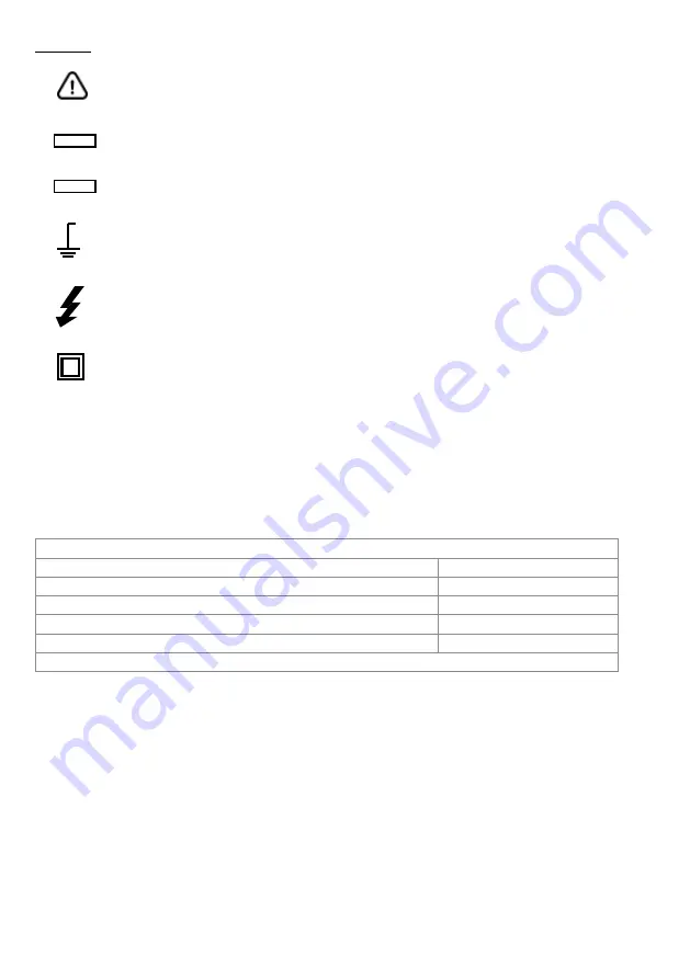
This symbol adjacent to another symbol, terminal or operating device indicates 

that the operator must refer to an explanation in the Operating Instructions to 

avoid personal injury or damage to the meter.

This WARNING symbol indicates a potentially hazardous situation, which if not 

avoided, could result in death or serious injury.

This CAUTION symbol indicates a potentially hazardous situation, which if not 

avoided, may result damage to the product.

This symbol advises the user that the terminal(s) so marked must not connected 

to a circuit point at which the voltage with respect to earth ground exceeds (in 

this case) 1000 VAC or VDC.

This symbol adjacent to one or more terminals identifies them as being associ-

ated with ranges that may, in normal use, be subjected to particularly hazardous 

voltages. For maximum safety, the meter and its test leads should not be handled 

when these terminals are energized.

This symbol indicates that a device is protected throughout by double insulation 

or reinforced insulation.

MAX

WARNING

CAUTION

Safety Instructions

This meter has been designed for safe use, but must be operated with caution. The rules 

listed below must be carefully followed for safe operation.
•  NEVER apply voltage or current to the meter that exceeds the specified maximum:

•  USE EXTREME CAUTION when working with high voltages.
•  DO NOT measure voltage if the voltage on the “COM” input jack exceeds 1000V above 

earth ground.

•  NEVER connect the meter leads across a voltage source while the function switch is in the 

current, resistance, or diode mode. Doing so can damage the meter.

•  ALWAYS discharge filter capacitors in power supplies and disconnect the power when  

making resistance or diode tests.

•  ALWAYS turn off the power and disconnect the test leads before opening the covers to 

replace the fuse or batteries.

•  NEVER operate the meter unless the back cover and the battery and fuse covers are in 

place and fastened securely. If the equipment is used in a manner not  

specified by the manufacturer, the protection provided by the equipment may be impaired.

Input Protection Limits

Function

Maximum Input

V DC or V AC

1000VDC/AC RMS

mA AC/DC

800mA 1000V fast acting fuse

A AC/DC

10A 1000V fast acting fuse

Frequency, Resistance, Capacitance, Duty Cycle, Diode Test, Continuity

1000VDC/AC rms

Surge Protection: 8kV peak per IEC 61010

Summary of Contents for 20250-66

Page 1: ...THE STANDARD IN PRECISION MEASUREMENT User Manual Digital IR Multimeter with Bluetooth Mobile App and NIST Traceable Calibration Model 20250 66...

Page 2: ...ions can be accessed A full description of its operation is available for download in the app The Digital IR Multimeter provides true RMS measurements and comes with a built in Thermal Imager and TFT...

Page 3: ...s meter has been designed for safe use but must be operated with caution The rules listed below must be carefully followed for safe operation NEVER apply voltage or current to the meter that exceeds t...

Page 4: ...al imager lens 15 Lens cover 16 Work light 17 Laser 18 Support plate 19 Battery cover lock 12 10 11 8 7 6 5 4 3 2 1 9 19 18 17 16 15 14 13 REL PEAK MAX Understanding the Push Buttons The 9 push button...

Page 5: ...of Automatic Manual mode 4 Analog bar graph 5 Indications associated with function keys 6 Indication of the system s time 7 Indication of measuring unit 8 SD card 9 Temperature measuring result 10 Ind...

Page 6: ...test lead banana plug into the negative COM jack Insert the red test lead banana plug into the positive V jack Read the voltage in the display AC DC Voltage Measurements CAUTION Do not measure DC volt...

Page 7: ...ead banana plug into the positive jack Read the resistance in the display Continuity Check WARNING To avoid electric shock disconnect power to the unit under test and discharge all capacitors before t...

Page 8: ...negative COM jack Insert the red test lead banana plug into the positive V jack Read the current in the display Press the MODE key to switch the AC DC and AC DC current Press the RANGE key to switch r...

Page 9: ...ts up to 600mA AC DC set the function switch to the yellow mA position and insert the red test lead banana plug into the A mA jack For current measurements up to 10A AC DC set the function switch to t...

Page 10: ...causes the meter to turn off Peak mode Non Contact AC Voltage Detector 100 to 1000V AC WARNING Risk of Electrocution Before use always test the Voltage Detector on a known live circuit to verify prop...

Page 11: ...hermal imager temperature measurement represents the center spot temperature of the scene 8 Highest temperature spot of the thermal imager temperature measurement represents the highest spot temperatu...

Page 12: ...or seen at a set distance the unit is rad The formula is this IFOV Pixel Size Lens focal length D S theoretical 1 IFOVtheoretical is the calculated spot size based on the pixel size of the Thermal Ima...

Page 13: ...s Palette mode Thermal imager has five kinds of palettes such as Press RIGHT MENU button to select one of the display color palettes Temp Unit Press RIGHT MENU button to set focus on this option and t...

Page 14: ...00 to 10 in 10 steps Auto Off Press RIGHT MENU button to set focus on this option In focus state use UP DOWN button to choose the time period after which the meter enters the sleep mode Bluetooth Conn...

Page 15: ...er s version Factory Set Select Factory Set option after pressing RIGHT MENU button The dialog box will be displayed as shown right Select YES button and system parameter will be reset Record measurem...

Page 16: ...imension appears at the top of the display on the right side You can zoom X1 for at least 10 measuring points X2 for at least 20 measuring points X3 for at least 40 measuring points and so on for maxi...

Page 17: ...C 5 4 F or 3 of reading Environment temperature 10 35 C object temperature 0 C Range Resolution Accuracy Protection against overcharge 50 Hz 60 Hz 61 Hz 1k Hz 6 000 V 0 001 V 0 8 reading 5 digits 2 4...

Page 18: ...0V Range Resolution Accuracy Protection against overcharge 50 Hz 60 Hz 61 Hz 1k Hz 30 00A 0 01A 0 8 reading 5 digits 2 4 reading 5 digits 1000 VDC ACrms 300 0A 0 1A 3000A 1A Function Test current Max...

Page 19: ...5 0 to 95 0 0 1 1 2 reading 2 digits Range Resolution Accuracy Protection against overcharge 60 00 nF 0 01 nF 1 5 reading 20dgt 1000 VDC ACrms 600 0 nF 0 1 nF 1 2 reading 8digits 6 000 F 0 001 F 1 5...

Page 20: ...in 175 x 85 x 55 cm Weight batteries included 19 oz 540g Power supply Battery type 1x7 4V rechargeable Li ION battery 2300mAh Battery charger power supply 100 240V AC 50 60 Hz 10VDC 1A Low battery ind...

Page 21: ...conditions for use Reference temperature 18 C to 28 C 64 F to 82 F Operating temperature 5 C to 40 C 41 F to 104 F Allowable relative humidity 80 RH Storage temperature 20 to 60 C 4 F to 140 F Storag...

Page 22: ...n the device with a soft damp and lint free cloth Ensure that no moisture enters the housing Do not use any sprays solvents alcohol based cleaning agents or abrasive cleaners only use clean water The...

Page 23: ...ements however your quality system or regulatory body may require more frequent calibrations To schedule your recalibration please contact InnoCal an ISO 17025 calibration laboratory accredited by A2L...

Page 24: ...For Product and Ordering Information Contact Toll Free 1 800 323 4340 Phone 1 847 549 7600 Fax 1 847 247 2929 ColeParmer com Digi Sense 24 1065DGMAN_20250 66 Manual Part No 00102 02...

Reviews: