background image

23 

Maintenance 

Simple preventive maintenance steps include keeping the thermometer clean. Protect it
from overload, excessive dirt, oil and corrosion.

Cleaning: If cleaning is necessary, use only a damp cloth with water only. Wipe only
the exterior of the control chassis.

CATALOG NUMBERS  

92000-01 

SERIAL NUMBER _______________________ 

DATE OF PURCHASE ___________________ 

Rev. 2 1/12/17 

99 Washington Street 
Melrose, MA 02176 

Phone

 781-665-

1400

Toll Free 1-800-517-8431

Visit us at www.T

estEquipmentDepot.com

Summary of Contents for 92000-01

Page 1: ...hannel Benchtop Data Logging Thermocouple Thermometer Model 92000 01 THE STANDARD IN PRECISION MEASUREMENT 99 Washington Street Melrose MA 02176 Phone 781 665 1400 Toll Free 1 800 517 8431 Visit us at...

Page 2: ...l 5 Active Display Screen 6 Main Menu 6 Global Settings 7 9 Channel Settings 9 13 Start Stop Logging 13 Copy to USB 13 Scan Setting 14 View Calibration Pts 14 DAQ Software installation 15 17 Safety 18...

Page 3: ...grid mounting clamp on the back of the device Unpacking Check individual parts against the list of items below If anything is missing or damaged please contact your instrument supplier immediately 1...

Page 4: ...ability to continue to move upward and downward through options is shown by gray arrows adjacent to the side bar menu and above and below the settings options 6 LEFT RIGHT Arrow Buttons The left and r...

Page 5: ...outside alarm if an external alarm is required 4 USB Communication Port This will be used to communicate with the DAQ software so the user can see a graph of the real time data as it is being logged b...

Page 6: ...This is the first sidebar menu that the user access s Button Navigation All sidebar menu s after this one will work in the same manner and will be able to be navigated as follows Up down buttons will...

Page 7: ...arms that have been enabled in the channel specific menu This will not disrupt temperature readings only disable audible alarms Power Failure Mode Power Failure Mode controls the multichannel process...

Page 8: ...yyyy or Mmm dd yyyy Upon entry into the screen a prompt to select the format appears Up and Down buttons toggle through the set date options and lay out options Enter selects the format Once the user...

Page 9: ...s for the channel highlighted in the sidebar Here the user may scroll through the twelve channels and gather information at a glance as well as select what channel to change the settings Alarm Setpoin...

Page 10: ...ata until the alarm temperature set points are reached or continue to log data after the value is reached Alarm Settings Within the Alarm Settings menu there are four available parameters to set Audib...

Page 11: ...channel Options J K T S R and E Alarm Setpoints Alarm Set Points are channel specific temperatures composed of a chosen low and high value that will trigger the alarm Upon entry the high set point is...

Page 12: ...e in this function While no settings can be changed the user must press Cancel to return to the sidebar menu Set Calibration Pts This setting should not be changed by the user This is a password prote...

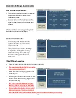
Page 13: ...ng logged the unit must stay on Pressing the Enter button while on this screen while data is being logged will stop the data log The user should ALWAYS stop the data log before copying to the USB Do n...

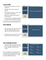
Page 14: ...Since no setting can be manipulated the only buttons when the sidebar menu is inac tive are the Up and Down arrows to toggle through the different channels Copy to USB Here the user will follow the o...

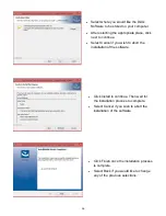
Page 15: ...e Select the next to continue with the installation of the software Select Cancel if you wish to abort the installation of the software We recommend that you read the terms and conditions before you a...

Page 16: ...Select Cancel if you wish to abort the installation of the software Click Install to continue Then wait for the installation process to complete Select Cancel if you wish to abort the installation of...

Page 17: ...is made the disconnect button will be selectable and the cur rent process temperature will be displayed 4 If there is a desire to only graph a selection of channels Just click the number in the channe...

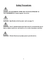
Page 18: ...ontact supplier for service WARNING Specifications for the power cord see page 19 WARNING Use of separate temperature limit control is recommended were a fault condition could occur and result in a fi...

Page 19: ...ductivity pollution occurs Installation category II local level connect to branch circuit and not directly to a main cir cuit such as a fuse panel Storage 32 to 140 F 0 to 60 C 5 to 80 RH noncondensin...

Page 20: ...of span or 1 C Types R S 0 2 of span Type T below 50 C 0 2 of span Accuracy span is 1000 F 540 C minimum Calibration ambient temperature 22 C 3 C Temperature Stability 0 1 C C rise in ambient maximum...

Page 21: ...Benchtop Data Logging Thermocouple Ther mometer will log data before it runs out of useable memory The numbers below were calculated as if all 12 channels are being logged at the same time If the user...

Page 22: ...22 Screen Flow Charts...
Page 23: ...aning If cleaning is necessary use only a damp cloth with water only Wipe only the exterior of the control chassis CATALOG NUMBERS 92000 01 SERIAL NUMBER _______________________ DATE OF PURCHASE _____...

Reviews: