background image

Cole-Parmer Instrument Co.

625 East Bunker Court

Vernon Hills, Illinois U.S.A. 60061-1844

(847) 549-7600

(847) 247-2929 (Fax)

800-323-4340

www.coleparmer.com

e-mail: techinfo@coleparmer.com

A-1299-0632

Edition 07


                                68X309908   Rev. 0   08/03 

THERMOCOUPLE  THERMOMETER

Dual J-T-E-K

®

MODEL 

NO.  91100-40

®

Summary of Contents for Dual J-T-E-K 91100-40

Page 1: ...r Court Vernon Hills Illinois U S A 60061 1844 847 549 7600 847 247 2929 Fax 800 323 4340 www coleparmer com e mail techinfo coleparmer com A 1299 0632 Edition 07 68X309908 Rev 0 08 03 THERMOCOUPLE TH...

Page 2: ...rmometer at the time of calibration was within specifications stated in the operating manual Model No __________________________ Serial Number ______________________ Date placed in service ___________...

Page 3: ...erature measurements in Celsius or Fahrenheit using a wide range of thermocouple types The temperature range for each type ther mocouple is listed in the following chart TYPE C F J 200 to 1000 328 to...

Page 4: ...9 9 F LCD with three four digit displays Two 2 blade female ANSI mini connector inputs Hold feature for temporarily retaining a reading Two point field calibration capability Low battery warning Store...

Page 5: ...DAMAGE TO UNIT VOLTAGES PRESENT AT THE THERMOCOUPLES MAY ALSO BE PRESENT ATTHE BATTERYTER MINALS ALWAYS DISCONNECTTHETHERMO COUPLE WHEN CHANGING BATTERIES TO PREVENT IGNITION OF A HAZARDOUS ATMOS PHER...

Page 6: ...curacy 150 C 0 25 of reading 1 C 2 F Linearization Conforms to NIST monograph 175 revised to ITS 90 Input Protection 50V rms Conversion Rate Reading 0 6 seconds per update Connector Two blade female A...

Page 7: ...atteries 227 grams 8 ounces Ingress protection Meets IEC 529 IP 54 for dust and water resistant enclosures Intrinsic safety This product is energy limited for intrinsically safe operation in hydrogen...

Page 8: ...BE PRESENT ATTHE BATTERYTER MINALS ALWAYS DISCONNECTTHETHERMO COUPLE WHEN CHANGING BATTERIES TO PREVENT IGNITION OF A HAZARDOUS ATMOS PHERE BATTERIES MUST ONLY BE CHANGED IN AN AREA KNOWNTO BE NON HAZ...

Page 9: ...S POINT BATTERY MUST BE CHANGED IF BATTERY VOLTAGE GOES TOO LOW DIS PLAY WILL GO BLANK See SPECIFICATIONS for battery type 1 Before changing battery turn instrument off and disconnect thermocouple s 2...

Page 10: ...rs have one wide blade and one narrow blade Do not force connector in back wards Connect thermocouple s to receptacle at top of instrument If only one thermocouple is being used it can be connected to...

Page 11: ...9...

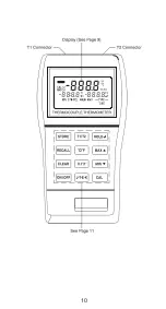
Page 12: ...10...

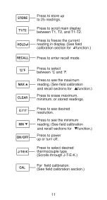
Page 13: ...11...

Page 14: ...ors as shown below should remain on for approximately one second 4 Use J T E K key to select the correct thermo couple and the C F key to select the desired scale This message also appears if a thermo...

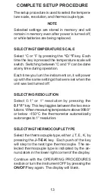
Page 15: ...er up with the same settings that were set when the unit was last turned off SELECTING RESOLUTION Select 0 1 or 1 resolution by pressing the 0 1 1 key This key toggles between the two reso lutions Whe...

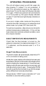
Page 16: ...the unit has been stored at an extreme ambient condition more time may be needed BASICTEMPERATURE MEASUREMENTS Check that the thermometer is turned on the probe s connected the desired resolution 0 1...

Page 17: ...left display to showT1 and the lower right display to show T2 MAXIMUM READINGS The maximum reading function displays the maxi mum reading since power up or since the last time the clear function was...

Page 18: ...cted to T2 the maximum reading will be shown in the lower right display If a higher maximum occurs while in the MAX mode the higher reading will be displayed To turn off the maximum reading press the...

Page 19: ...AR key then the MAX key The maximum memory will be cleared MINIMUM READINGS The minimum reading function displays the mini mum reading since power up or since the last time the clear function was used...

Page 20: ...ading press the MIN key again If you are in the single probe differential mode momentarily press the MIN key The MAX and MIN annunciator turns on and both the maximum and minimum readings appear in th...

Page 21: ...the present T1 or T2 reading 1 Place probe at first measurement point 2 Press the T1 T2 key to store this reference tem perature The T and M annunciators will be on and the reference temperature will...

Page 22: ...ress the HOLD key to retain the reading on the display Press HOLD key again for normal operation Maximum Minimum Hold Readings Press the MAX key then press the HOLD key To turn off the HOLD function a...

Page 23: ...about 3 seconds After 25 stored readings the next time the STORE key is pressed the main display will indicate FULL RECALL READINGS This function allows the stored readings to be re called RECALL sho...

Page 24: ...apabil ity to hold calibration values even while power is off or the battery is removed When you restart there is no need to recalibrate Each of the four thermocouple types may be indi vidually calibr...

Page 25: ...play will indicate T1 or T2 as applicable For proper calibration the following conditions must be observed The slope point must be a higher temperature than the offset point The difference must be at...

Page 26: ...et cali bration in and advance to the slope calibration To return to normal operation press any key ex cept CAL or HOLD 5 Slope Calibration Place the probe at the higher reference temperature 6 Allow...

Page 27: ...bration Momentarily press the CAL key to enter the calibration mode the CAL an nunciator will flash The temperature is displayed on the main display and Lo is displayed on the lower left display Lo si...

Page 28: ...for that input will also be skipped 7 Slope Calibration Place the probe s at the higher reference temperature 8 The temperature is displayed on the main dis play and Hi is displayed on the lower left...

Page 29: ...remain lit 13 This completes the two point calibration 14 To return to normal operation press any key except ON OFF key or the CAL key MatchingT1 andT2 Procedure This procedure requires both probes t...

Page 30: ...field calibration operation Lockout Procedure 1 Turn the thermometer off 2 Simultaneously press and hold the CAL and the CLEAR keys down and momentarily press the ON OFF key Continue to hold the CAL...

Page 31: ...not clean with abrasives or solvents Use mild detergents never immerse nor use excessive fluid BATTERIES If there is no display when the thermometer is turned on check condition of the two AA batteri...

Page 32: ...NTRINSEQUE There are no internal adjustments or user replace able parts If Err followed by the numbers 1 through 9 is dis played see example below return unit for service Note that Err alone may be di...

Page 33: ...lay when Check condition of turned on batteries Check that batteries are inserted properly Display shows Out of range indication Display shows Open thermocouple OPEn connection Display shows If displa...

Page 34: ...t the above model is in conformity to the following harmonized standards and directives Applicable Applicable Manufacturer s Directives Specifications Report Number 89 336 EEC EN61326 1 A1 1998 TR9648...

Page 35: ...t charges and delays contact the seller or Manufacturer for authorization and shipping instruc tions before returning the product either within or outside of the warranty period When returning the pro...

Page 36: ...08500 55 Penetration probes 4 in long x 0 156 in dia sharp tip 5 second time constant Type J 08517 65 Type K 08516 65 TypeT 08500 65 Surface probes 10 in long with 5 8 in dia alumi num and ceramic tip...

Reviews: