background image

System Inaccurate

 (continued)

Mounts, Platform or Cart Not Shimmed or Supported Properly to
Provide Equal Load at Each Load Cell:

On MOBILE applications, side pressure on a wheel or tongue can cause inaccurate
readings.  Make sure wheels are on a level surface and there is no draw bar pull on
tongue.

On PLATFORM applications, use a large screwdriver or pry bar to pry up on the corners
of the deck.  If one of the corners has noticeably less resistance, the deck may require
shimming or adjustment of the leveling screws (if present).

On FEED BIN applications, rock the bin back and forth, and check the mounts for any
movement or play.  Insure that each mount has equal pressure and is secured to the slab.

Defective Load Cell:

If you suspect that you have a defective load cell, test them using the procedure on page
11.

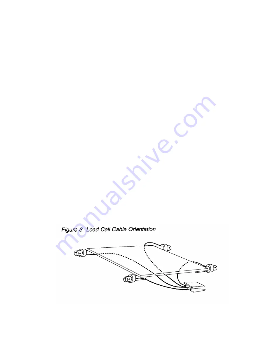
Load Cell Up-Side Down:

If one load cell is mounted up-side down, the corner with the upside-down cell would read
negative.  Visually check load cells for proper orientation (see below).  The load cell should
deflect the same direction as the black arrow on the end of the cell.


NOTE: Each load cell is manufactured so that the cable comes off of the same side of the

cell (see diagram).  Decals are also placed on the same side of each load cell.

Summary of Contents for EZ 150

Page 1: ...Scale System Troubleshooting Guide for Digi Star Scales with EZ 150 EZ 210 and EZ 320 Indicators F3214B December 1997 ...

Page 2: ...shes RANGE 3 Indicator Will Not Come On 4 Indicator Will Not Weigh 6 Indicator Unstable Drifts 6 System Inaccurate 7 Indicator Will Not Balance zero 9 Testing the Indicator Using Simulator 9 Inspect Junction Box Wiring 10 Test the Junction Box 10 Testing the Load Cells 11 Load Cell Resistance Chart 12 ...

Page 3: ...EZ 150 EZ 320 EZ 210 EZ Indicators ...

Page 4: ...roubleshooting flowcharts and step by step procedures for troubleshooting problems commonly found with most Digi Star scale systems Required Tools Multimeter AC DC Volts and Resistance Simulator sold by Digi Star Small Screwdriver straight blade 2 Phillips Screwdriver Digi Star Scales The basic elements of the Digi Star scale system are Indicator Load Cells 3 to 8 cells per system Junction Box Pow...

Page 5: ...h RANGE replace the indicator 3 If indicator stops flashing RANGE and stabilizes at a weight reconnect the junction box and inspect the junction box wiring see page 10 4 If all connections in the junction box appear good and the display continues to flash RANGE disconnect all load cell wires from junction box 5 If the display continues to flash RANGE and the indicator checked out OK the junction b...

Page 6: ...ircuit Breaker etc Check 12V Voltage at Source Check Fuse in Supply Check 110 VAC Outlet Bad Battery Check for Bad AC DC Converter see note Good Good Bad Good Bad Indicator will not come on NOTE A battery may check good with a meter but still may not be strong enough to power the system Indicator Will Not Come On Two conditions cause the indicator not to come on They are No Power to Indicator 12 V...

Page 7: ...sure between PIN 1 POS and PIN 2 NEG The meter should read between 10 5 and 14 5 volts DC Mobile Applications A bad vehicle ground or a weak battery can cause problems even if voltages check OK Connect the indicator to a known good power source your service vehicle battery is a good choice If the indicator works OK check into the vehicle battery and ground connections or replace the battery If a t...

Page 8: ...igned to compensate for slow changing variations on an empty scale i e snowfall or temperature drift Zero Track is not functional while weight is applied or in NET mode 1 If rapid or intermittent changes in the display occurs test the indicator by disconnecting the junction box from the indicator and short pins 2 and 3 on the load cell jack If the symptoms persist replace the indicator 2 Inspect t...

Page 9: ... from the others then continue to one of the other possibilities in this section Indicator with Wrong Set Up or Miscalibrated Verify that the indicator has the proper set up Compare the system configuration size type and number of load cells to the decal on the bottom of the indicator Inaccurate calibration If the indicator needs re calibration it is best to contact your dealer first See scale ope...

Page 10: ...esent On FEED BIN applications rock the bin back and forth and check the mounts for any movement or play Insure that each mount has equal pressure and is secured to the slab Defective Load Cell If you suspect that you have a defective load cell test them using the procedure on page 11 Load Cell Up Side Down If one load cell is mounted up side down the corner with the upside down cell would read ne...

Page 11: ... load cells and test junction box See page 10 4 Test Load Cells See page 11 Stability Feature is On Motion Detection EZ Series indicators will not allow you to balance if the stability feature is turned ON and the display is unstable NOTE On EZ Series indicators a will appear under the word Motion to indicate an unstable condition Testing the Indicator Using Simulator 1 With the power ON disconnec...

Page 12: ...oad cell wires from junction box 2 If the failure mode does not change and the indicator checked out OK earlier page 10 the junction box is defective Be sure to test load cells using an ohm meter see page 11 to assure that they have not been damaged 3 If the display stops flashing and stabilizes at a weight the junction box is OK Testing the Load Cells Using Working Indicator Junction Box 1 Discon...

Page 13: ...problem For best results test load cells using a working indicator 1 Identify the load cell type and use the chart on page 12 to determine the resistance values between the wires on the load cell 2 Using an ohm meter measure the resistance between leads on the load cell 3 Replace the load cell if it measures more than 15 above or below the value listed in the chart on page 12 NOTE Bad load cells w...

Reviews: