T
h
e
C
o
n
n
ec
tC
o
re
8X
S
ys
te
m
-o
n
-m
o
d
u
le
P
o
w
er
in
te
rfa
ce
s
C
o
n
n
ec
tC
o
re
®
8X
S
ys
te
m
-o
n
-M
o
d
u
le
H
a
rd
w
a
re
R
ef
er
en
ce
M
a
n
u
a
l
1
8
Output power rails
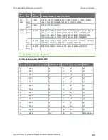
The following table lists the electrical specifications of all output power rails for the ConnectCore 8X:
Device
SOM power rail
Used
internally
in the SOM
Output voltage (V)
Accuracy (%)
Max
output
current
(mA)
1
Turn-on time (us)
Turn-off time (us)
Min
Typ
Max
Min
Typ
Max
Min
Typ
Max
Min
Typ
Max
PMIC
SW6
1V8
YES
-
1.80
-
-2.0
-
2.0
2500
36
160
279
-
-
-
SW7
3V3
YES
-
3.30
-
-2.0
-
2.0
2500
-
-
200
-
-
-
LD01
VCC_SCU_1V8
YES
-
1.80
-
-3.0
-
3.0
400
-
-
500
-
-
2500
LD02
VDD_EMMC0
YES
-
3.30
-
-3.0
-
3.0
400
-
-
500
-
-
2500
LD03
LDO3
NO
1.5
-
5.0
-3.0
-
3.0
400
-
-
500
-
-
2500
LD04
LDO4
NO
1.5
-
5.0
-3.0
-
3.0
400
-
-
500
-
-
2500
VSNVS
VCC_
LICELL
(coin cell
charger)
2.6 V
to
3.6 V
YES
1.8
-
3.6
-3.0
-
3.0
0.060
1.8 V
to
2.5 V
YES
-4.0
-
4.0
Note
For a complete description of the electrical characteristics of the different output power rails (PMIC regulators), see the NXP PF8x00 datasheet.
1
The maximum output current involves both external and internal circuitry. For those regulators that are used internally in the SOM, the current
available outside it will be lower.
2
Turn-on time for this regulator is specified for VSW7 = 1.8 V. In the ConnectCore 8X this regulator is configured to work at 3.3V, so a higher turn-on time
may be observed.


