The ConnectCore 8X System-on-module
Power interfaces
ConnectCore® 8X System-on-Module Hardware Reference Manual
19
System power-up sequence
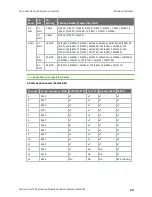
When the power supply is connected to the ConnectCore 8X module, the PMIC and the MCA are the
first components to be powered up. VSYS and VSYS2 are PMIC supplies, while VCC_MCA is the Digi
Microcontroller Assist input power line. The system power-up sequence is as follows:
1. The MCA starts to run as soon as it is powered up. After a certain programmable time, it will
release the PWRON line of the PMIC (PMIC power on/off).
2. Once the PMIC is switched on, it starts an initialization process as determined by its OTPs.
Finally the CPU reset line, which is controlled by both the PMIC and the MCA, is released.
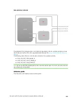
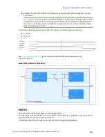
The following time diagram shows the power-up sequence.
RTC power and coin cell charger
The VCC_LICELL pin supports coin cell charger functionality. This pin is also the input power supply
for an always-on regulator of the PMIC (VSNVS) that feeds the low-power mode circuitry of the CPU. In
the ConnectCore 8X module, the low-power modes of the system (RTC) are supported by the on-
module MCA, not by the i.MX 8X CPU. Therefore, in order to reduce the static power consumption of
the SOM, do not power the VSNVS regulator in low power mode. The coin cell should only power the
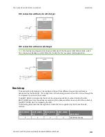
VCC_MCA power domain through the diode configuration as shown in the following diagrams.
If the coin-cell charger functionality is mandatory, place a reverse diode between VCC_LICELL and the
coin cell.


