Interfacing protocols
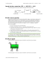
Sample wireless connection: DTE <--> DCE DCE <--> DCE
XBee-PRO 900HP RF Modem User Guide
19
Sample wireless connection: DTE <--> DCE DCE <--> DCE
The following figure shows a typical wireless link between DTE and DCE devices:
RS-485 (2-wire) operation
Note that with the RS-485 variant of the XBee-PRO 900HP RF Modem, the RF Modem is defaulted with
the
D7
command (AT parameter) to 7. This parameter controls the TX enable signal and allows the
modem to output any data in the DO buffer to the host device for the RS-485 interface. In the event
that the parameter is accidentally changed, which would halt RS-485 communication, a USB mini
cable should be plugged into the modem to reconfigure it. You can reconfigure by using XCTU.
With the USB plugged in:
1. Open XCTU and select the Com port of the USB.
2. Select the Terminal tab and type '+++'. The system will respond with 'OK'.
3. Type “ATD77” then <Enter>, and the system will respond with 'OK'. Type “ATWR” then <Enter>,
and the system will respond with “OK”.
4. Type “ATCN” then <Enter> to exit command mode, and the system will respond with “OK”.
5. Unplug the USB and return to the existing RS-485 interface. The 900HP RF Modem is now ready
to communicate in RS-485 model.
Note
Failure to enter AT Command Mode is most commonly due to baud rate mismatch. Ensure the
“Baud" setting on the “PC Settings” tab matches the BD (Interface Data Rate) setting of the RF modem
(by default, BD parameter = 3, which is associated with 9600 baud).
RS-485 pin signals
The following figure shows the pins used on the RS-485 (2 wire) Phoenix 6-pin connector:
The following figure shows the pins used on the RS-485 (2 wire) Phoenix 6-pin connector:


