Interfacing protocols
RS-485 wiring diagram
XBee-PRO 900HP RF Modem User Guide
20
Phoenix
6 pin
RS-485
name
Description
Implementation
1
TX/RX+
Negative
Data Line
Transmit serial data to and from the RF modem
2
TX/RX-
Positive Data
Line
Transmit serial to and from the RF modem
5
GND
Ground
Signal
Ground
6
PWR
Power Signal
Optional power input (protection circuitry to prevent back
flow from other power sources internal to the board)
3, 4
Not Used
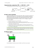
RS-485 wiring diagram
The following figure shows the RF Modem in an RS-485 (2 wire) half duplex:
RS-485 (4-wire) operation and RS-422 operation
Note that with the RS-485 variant of the XBee-PRO 900HP RF Modem, the RF Modem is defaulted with
the
D7
command (AT parameter) to 7. This parameter controls the TX enable signal and allows the
modem to output any data in the DO buffer to the host device for the RS-485/422 interface. In the
event that the parameter is accidentally changed, which would halt RS-485 communication, a USB
mini cable should be plugged into the modem to reconfigure it. You can reconfigure by using Digi's
XCTU.
With the USB plugged in:
1. Open XCTU and select the Com port of the USB.
2. Select the Terminal tab and type “+++”. The system will respond with “OK”.
3. Type “ATD77” then <Enter>, and the system will respond with “OK”.


