background image

Digicare Biomedical Technology


Operators Manual Multi-parameter Patient Monitor  " LifeWindow Lite LW8 " 

42


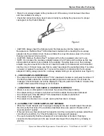
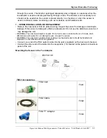
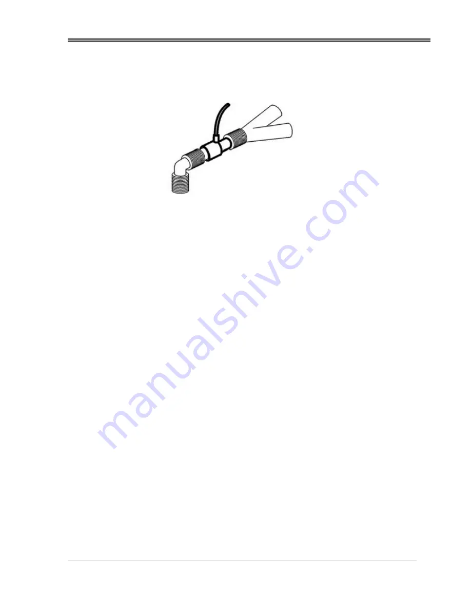
•  Place the on-airway adapter at the proximal end of the airway circuit between the elbow 
   and the ventilator circuit wye. 
•  Check that connections have been made correctly by verifying the presence of a proper 
   capnogram on the Patient Monitor. 


Figure 3


•  CAUTION: Always insert the Sample Cell of the Sample line into the Sample Cell 
   Receptacle on the MicroFlow™ CO2 sidestream module before inserting the on-airway  
   adapter into the ventilator circuit. Failure to follow this, may introduce a leak in the circuit,  
   thereby reducing set minute volume. 
•  CAUTION: Remove the MicroFlow™ sample cell from the receptacle when not in use. 
•  NOTE: Do not place the on-airway adapter between the ET tube and the elbow as this may   
   allow patient secretions to accumulate in the adapter. If pooling does occur, the on-airway   
   adapter may be removed from the circuit, rinsed with water (or sterile water) and reinserted  
   into the circuit. If rinsed, make sure that no water has entered the sampling tubing. If so, blow   
   out water or replace the sample line. To prevent moisture from draining into the on-airway   
   adapter kit tubing, always place the on-airway adapter tubing in an up position (see Figure 3). 


6 – CHECK SAMPLE LINE MESSAGE 

•  The sample flow rate of the MicroFlow™ CO2 sidestream module is continually monitored. If   
    the flow rate falls outside the nominal operating range and continues for 15 seconds, the   
    message “Check Sample Line” will be displayed. The pump will shut off after 2 minutes if the   
    condition that caused this change is not corrected. 


7 – CONDITIONS THAT CAN CAUSE A CHANGE IN FLOW RATE 

•  Water, mucous or other patient contaminate has entered the sample tubing. 
•  The sample tubing is crimped or pinched so that the sample flow rate has decreased. 
•  The exhaust port of the MicroFlow™ CO2 sidestream module is obstructed. 
•  The sample line is damaged. 
•  The sample line has been cut, or split, causing the flow rate to increase. 


8 –CLEARING THE “CHECK SAMPLE LINE” MESSAGE 

•  When the “Check Sample Line” message is displayed, the user should inspect the sample 
   line kit to verify that none of the conditions described above are present. Replace with a 
   new sample kit if needed. 
•  If the user removes the sample cell for inspection and then reinserts the sample cell without 
   correcting the condition, the “Check Sample Line” message will reappear. 
•  The user should verify that the exhaust port is not obstructed or blocked. If tubing is 
   connected to the exhaust port, the user should also inspect the tubing for any crimping or 
   pinching. 
 

Summary of Contents for LifeWindow Lite LW8

Page 1: ......

Page 2: ...31 Section 6 CO2 Mainstream Monitoring A Overview 32 Section 6 1 CO2 Mainstream Monitoring A Principle of Operation 32 B Indications for Use 32 C Patient Connections 33 D Monitoring CO2 36 Section 6 2...

Page 3: ...ble regulations respecting the installation and operation of the monitor be observed C WARRANTY All products manufactured by Digicare Biomedical Technology Inc are warranted to be free from defects in...

Page 4: ...rt and is not DEFIBRILLATION PROOF The Temperature connection is type BF applied part and is not DEFIBRILLATION PROOF The SpO2 is type BF applied part and is not DEFIBRILLATION PROOF All other patient...

Page 5: ...raphic Interface displays 6 user selectable physiologic waveforms numeric values indicators alarm messages and physiologic parameters menu 2 ALARM DISABLE dedicated pushbutton 3 FREEZE TRACES dedicate...

Page 6: ...rt Rate monitoring 14 Invasive Pressure Channel 1 connector Accepts pressure transducer cable to invasive determination and monitoring of blood pressure 15 FIO2 connector Accept cable and sensor to In...

Page 7: ...ndard AT type keyboard used only to service purposes 22 Auxiliary Connector Supply analog output signals trigger signals and one RS232 communication port 23 Ethernet Connector Connection to Ethernet n...

Page 8: ...speed of 25mm s 32 Fourth waveform user selected area showing SpO2 waveform in Thin Line Style with Pulse Level strength scale 1 to 8 sweep speed of 25mm s 33 Fifth waveform user selected area showing...

Page 9: ...icator will light green and the BATTERY status indicator will light green if the battery is fully charged or yellow if charging Power on the unit by double clicking the ON switch 19 on the rear panel...

Page 10: ...o standard applications As the user changes Alarm Limits and other settings the LifeWindow Lite LW8 will save the changes when turned off Next time the unit is turned on the last saved settings will r...

Page 11: ...e 3 electrodes in the patient More details in Section 4 A visual indicator and a beep Sound indicates R wave detection and the ECG waveform and Heart Rate reading are displayed J SpO2 MONITORING The S...

Page 12: ...ulse Upper Limit 140 BPM NIBP Pulse Lower Limit 60 BPM The widest cuff that can be placed on the patient without extending beyond the joint should be selected Cuff width should be 40 60 of limb circum...

Page 13: ...sducer at the heart level axial line Additional information in Section 9 The message ZERO TRANSDUCER is displayed until a zero calibration is executed Open the TRANSDUCER input to the air Local Atmosp...

Page 14: ...SAVE DATA At the end of monitoring touch the System menu and Patient Management menu Touch Discharge Patient button Press Yes to confirm Press Yes to save the patient data Make sure the selected dire...

Page 15: ...correct DPI Set Charting Speed Options are 6 25 12 5 25 50 100 and 200 mm s Set Scale Changing scale will change the amplitude of the ECG in the printout Options are 2 5 5 10 20 40 80 and 160 mm mV As...

Page 16: ...ient can be admitted any time after start monitoring To save the patient s data touch in the System menu and touch in the Save Patient Vital Signs Report If the current patient is not admitted at this...

Page 17: ...Start click Run type sysdm cpl and then click OK 3 CHANGE COMPUTER NAME AND JOIN A DOMAIN OR A WORKGROUP To change a computer name and to join a domain or a workgroup follow these steps Warning Befor...

Page 18: ...oup is Workgroup Then the next page requires the domain name to which the computer is to be added Also the next page requires the username and the password of an account that has the rights to add a c...

Page 19: ...y installation of the printer driver Occasionally we are required to install the printer manually 1 Connect the printer to the PC and power both on 2 Click Start Settings and then Printers and Faxes 3...

Page 20: ...nology Operators Manual Multi parameter Patient Monitor LifeWindow Lite LW8 19 7 Select the port you have the printer plugged into and click Next 8 Select the Manufacturer on the left and the Printer...

Page 21: ...hnology Operators Manual Multi parameter Patient Monitor LifeWindow Lite LW8 20 9 Enter a Printer Name Click Next 10 If you d like to share the printer on the network click on Share name and enter a f...

Page 22: ...rint a test page click Next Otherwise click No then click Next 12 Click Finish to complete the printer install 13 You now have a printer installed 6 CONNECT TO A NETWORKED PRINTER 1 Click Start Settin...

Page 23: ...click OK Type the printer name or browse for it 1 Click Connect to this printer 2 Do one of the following Type the printer name using the following format printserver_name share_name Browse for it on...

Page 24: ...folder highlighted click Share This Folder 3 In the Sharing tab of the Properties dialog box select Share This Folder On The Network 4 Provide a descriptive name for the folder This name should make i...

Page 25: ...om DIGICARE with the following part number ECG Accessories Description P N ECG patient cable 10 length 3 Leads Digicare EC101 Set of 3 ECG lead wires with snap in 40 length for Digicare Patient Cable...

Page 26: ...the ECG leads to the electrodes ensure that the leads are in the correct ECG patient cable position Connect the leads to the ECG patient cable The ECG leads and patient cable connector are color coded...

Page 27: ...activated reduces the noise present in the ECG waveform that is displayed on the screen It does NOT improve the QRS detection and Heart Rate count To enable or disable the Mains Notch and Digital Filt...

Page 28: ...nsitivity Heart Rate range and Heart Rate Average The Average options are 8 16 32 and 64 Beats Adult mode sensitivity 0 3mV QRS amplitude Adult mode Heart Rate Range 5 to 220 BPM Adult mode Heart Rate...

Page 29: ...anges in absorption caused by pulsations of blood are used to determine Arterial Saturation SpO2 and Pulse Rate PR A PATIENT CONNECTIONS To ensure conformance with all safety and performance use only...

Page 30: ...he plastic hinged cover to prevent accidental cable disconnection If using 3 cable sensors Connect the sensor patient cable into the LifeWindow Lite LW8 SpO2 side panel connector 12 Push the connector...

Page 31: ...h some patients Loss of pulse can occur if The sensor is to tight There is excessive illumination e g a surgical or bilirubin lamp or direct sunlight The sensor is placed on an extremity with a blood...

Page 32: ...Limit 140 PPM Pulse Lower Limit 60 PPM Change the Pulse Alarm Limits in the SpO2 menu Pulse Upper Limit Range 5 to 450 PPM or OFF non overlapping Pulse Lower Limit Range 0 to 445 PPM or OFF non overl...

Page 33: ...y using the infrared absorption technique The principle is based on the fact that CO2 molecules absorb infrared IR light energy of specific wavelengths with the amount of energy absorbed being directl...

Page 34: ...ally check the MainFlow CO2 sensor and tubing for excessive moisture or secretion buildup While using the MainFlow CO2 sensor a system leak such as that caused by an uncuffed Endotracheal tube or a da...

Page 35: ...Stream MainFlow sensors Low Dead Space for Neonatal Part Number CAP113 For intubated patients with endotracheal tube diameters less than or equal to 4 mm Adds less than 1 cc of deadspace Weight 9 1 g...

Page 36: ...tion of the connector back and remove Note Do not remove by pulling cable The CO2 monitoring screen is automatically configured with the CO2 indicator area CO2 traces scales and CO2 alarm messages Wai...

Page 37: ...unction and ETCO2 insCO2 and Respiration Rate measured values with all alarm limits and settings in the defaults values or the last saved settings 1 CO2 WAVEFORM AND SCALE The CO2 waveform traces are...

Page 38: ...Indicates the Barometric Pressure or gas compensations have not been set since power on This message normally flashes quickly after power on of the sensor and is automatically cleared as the sensor s...

Page 39: ...ate that is used to measure the CO2 of non intubated and intubated patients Because of its unique design response is fast and there is less chance of erroneous artifact data The analyzer portion of th...

Page 40: ...entilator circuit CAUTIONS Electrical Shock Hazard the MicroFlow sidestream CO2 Module is not user serviceable Refer servicing to qualified personnel Follow precautions for electrostatic discharge ESD...

Page 41: ...tware of the unit The LifeWindow Lite LW8 screen with internal MicroFlow CO2 sidestream module installed displays the CO2 indicators and waveform after turned on It displays a Pump is Off message unti...

Page 42: ...in the MicroFlow CO2 sidestream Module Keep the MicroFlow airway adapter exposed to room air and away from all sources of CO2 including the ventilator the patient s breath and your own Touch in the C...

Page 43: ...g always place the on airway adapter tubing in an up position see Figure 3 6 CHECK SAMPLE LINE MESSAGE The sample flow rate of the MicroFlow CO2 sidestream module is continually monitored If the flow...

Page 44: ...hange the CO2 waveform scale touch the CO2 menu and select the desired waveform scale The options are 0 to 5 mm Hg 0 to 10 mmHg 0 to 50 mmHg and 0 to 100 mmHg 2 CO2 ALARM LIMITS CO2 Alarm Limits are s...

Page 45: ...e and airway adapter and perform a Zero calibration process Zero Error Indicates the Zero calibration process was not successful Clean or change the airway adapter Disconnect and reconnect the MicroFl...

Page 46: ...d the joint should be selected Appropriate sized cuffs may be selected based on published guidelines that cuff width should be 40 60 of limb circumference The cuff should be wrapped for a snug fit Ove...

Page 47: ...the cuff fits snugly and evenly and the bladder of the cuff is over the popliteal artery Cuff 3 showing artery position and circumference measurements NIBP Cuff 1 3 6cm 1 2 2 4 in Plastic for neonatal...

Page 48: ...LW8 47 NIBP Cuff 6 8 13cm 3 2 5 1 in Cloth BP005 NIBP Cuff 7 12 19cm 4 7 7 5 in Cloth BP003 NIBP Cuff 8 17 25cm 6 7 9 8 in Cloth BP004 NIBP Cuff 9 28 40cm 11 0 15 7 in Cloth BP002 NIBP Cuff 10 31 40cm...

Page 49: ...le finish is decremented in display 4 ADULT NEONATAL MODE SELECTION The Mode adult neonatal selection affects the NIBP operation For Cuff sizes 1 2 3 4 and 6 the NEONATAL mode should be selected For C...

Page 50: ...fact is affecting the NIBP determination Time Too Long Indicates the NIBP cycle is lasting too long for the NIBP determination and was aborted SECTION 8 TEMPERATURE MONITORING The LifeWindow Lite LW8...

Page 51: ...IGH Indicates the Temperature value is higher than the selected Temperature Upper Limit SECTION 9 INVASIVE PRESSURE MONITORING The LifeWindow Lite LW8 can have 1 or 2 Invasive Pressure Channels instal...

Page 52: ...P cable for disposable transducer IBP005 IBP disposable transducer with line monitoring kit Sensitivity 50 V V mmHg IBP006 IBP disposable transducer without line Sensitivity 50 V V mmHg IBP007 B PRESS...

Page 53: ...tions are 30 to 30 mmHg 0 to 30 mmHg 0 to 60 mmHg 0 to 90 mmHg 0 to 120 mmHg 0 to 180 mmHg 0 to 240 mmHg 0 to 300 mmHg 30 to 90 mmHg 60 to 120 mmHg 90 to 150 mmHg 120 to 180 mmHg 150 to 210 mmHg 180 t...

Page 54: ...lly and Heart Rate is being displayed Note When using the ECG as trigger source for IP the Invasive Pressure Pulse Indicator is NOT displayed E PULSATILE STATIC MODE The LifeWindow Lite LW8 Invasive P...

Page 55: ...the selected Systolic Lower Limit IP HIGH SYSTOLIC Indicates that Systolic value is higher than the selected Systolic Upper Limit IP LOW DIASTOLIC Indicates the Diastolic value is lower than the selec...

Page 56: ...damage or electrolyte leakage If the sensor is damaged obtain a replacement Do not use the defective sensor as it may damage the unit WARNING The sensor electrolyte is caustic Do not let it come in co...

Page 57: ...to make a 2 point calibration on FIO2 is displayed Press Yes In the Low Point FIO2 Calibration screen select the O2 concentration default 21 Make sure the oxygen sensor is exposed to the selected O2...

Page 58: ...ed humidifier are directed past a sensor teed into a breathing circuit 1 3 PRESSURE Virtually all gas sensors and monitors measure the partial pressure not the percentage of the gas that they sense Th...

Page 59: ...QUIREMENTS AC voltage Input 100 240 VAC 50 60 Hz max 80W Universal Power Input C ECG Lead Selection I II III Standard lead configuration Input Isolation Isolated from Ground related circuits by 4KV rm...

Page 60: ...perating Modes Manual Automatic Stat Auto Repeat Cycles 1 99 minutes Stat Cycle 1 4 minutes Systolic Range Adult 60 250 mmHg Neonatal 40 130 mmHg Diastolic Range Adult 40 220 mmHg Neonatal 20 90 mmHg...

Page 61: ...iration Rate Accuracy 1 breath Calibration No routine user calibration required An airway adapter zero is required when changing to a different style of airway adapter Compensations for Expired O2 bal...

Page 62: ...uracy 2 F S Isolation Isolated from ground related circuits by 4KV RMS 5 5KV peak I FIO2 Range 0 100 oxygen Accuracy 2 of full scale at constant temperature and pressure Response Time 90 in less than...

Page 63: ...monitor Do not touch or rub the display panel with abrasive cleaning compounds instruments brushes rough surfaced materials or make contact with anything that can scratch the panel B PROBES The probes...

Page 64: ...odium hypochlorite bleach a 2 gluteraldehyde solution ammonia mild soap or disinfectant spray cleaner such as Steris Coverage Spray HB Wipe down with a clean water dampened cloth to rinse and dry befo...

Page 65: ...the following conditions 1 Inadequate power or power failure 2 Neglect abuse or misuse of equipment 3 Servicing of equipment by person s other than DIGICARE INC 4 Any unit opened or tampered with with...

Reviews: