18
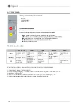
2.2 FRONT PANEL
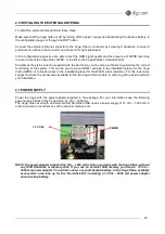
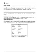
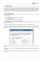
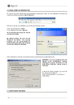
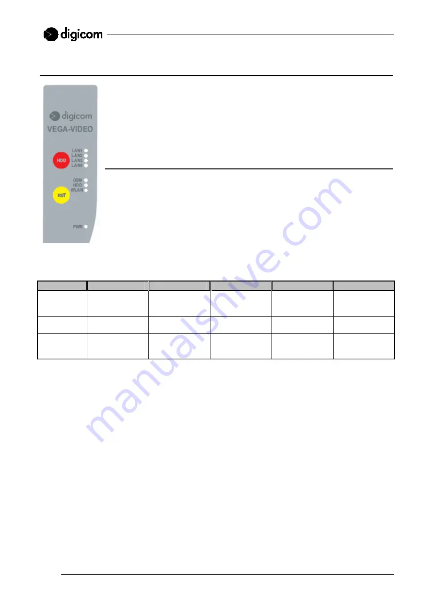
The Vega Video’s front panel consists of:
•
8 LEDs
•
1 HDD button
•
1 RST button
2.3 LED DESCRIPTION
Eight LED options indicate a different camera status, as follows:
•
LAN1, 2, 3, 4:
information on the relevant LAN port activity
•
GSM:
information on GSM registration (only for the Vega Video GPRS)
•
HDD:
information on the Hard-disk or memory stick connection
•
WLAN:
information on the LAN wireless connection
•
PWR:
Vega Video’s power
The LEDs can act as follows:
LAN 1, 2, 3, 4
GSM
HDD
WLAN
PWR
OFF
LAN port not in
use
GSM unit is
OFF
External
memory is not
active
Image capture
is OFF
Vega Video is
OFF
Blinking
LAN port activity
GSM unit is
registered
-
Image capture
is ON
-
ON
LAN port is
connected
Registered to
the GPRS
network
External
memory is
active
-
Vega Video is
ON
When the Vega Video is powered, the device goes through the following stages:
1. Vega Video’s power: PWR LED is ON.
2. Start of the Operating System: GSM, HDD and WLAN LEDs stay ON for about 15 seconds.
3. GSM unit identification.
4. WLAN unit identification: WLAN LED blinks immediately in case of WiFi problems.
5. Start of the image capture after about 2 minutes: blinking WLAN LED.

