Chapter 4: Focusrite D3
17
Meters
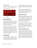
The meters indicate gain reduction (the top
meter) and output level (the bottom meter). The
Gain Reduction meter indicates the amount of
gain reduction in dB. The Output Level meter
indicates the output signal level in dB.
In Stereo mode, two Output Level meters ap-
pear, one for each channel. However, a single
Gain Reduction meter is used for both channels,
since the D3’s RMS detector uses a composite
control signal.
A red Clip Indicator appears to the right of the
output meter(s). Clicking on the Clip Indicator
clears it. Alt-clicking (Windows) or Option-
clicking (Mac) clears both channels when the
plug-in is used in stereo.
Metering indicators:
• Green indicates nominal levels.
• Yellow indicates pre-clipping at –6 below
full scale.
• Red indicates a full scale signal (clipping).
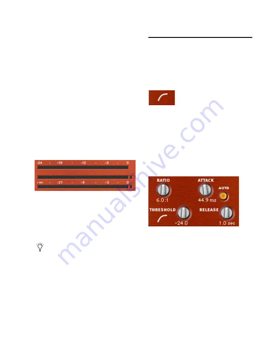
D3 Compressor Controls
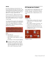
The Compressor icon, which represents a com-
pression curve, acts as a three-state switch for
enabling, disabling, or bypassing the compres-
sor. Its current state is indicated by the icon’s
color.
• White indicates enabled. In this state the
compressor is active and using available
DSP resources.
• Black indicates disabled. In this state, the
compressor is not using DSP resources.
• Gray indicates bypassed. In this state the
compressor is not active, but is still using
available DSP resources.
Meters
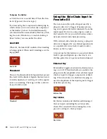
The Plug-in window includes a Clip LED
that lights red to indicate plug-in clipping.
The Plug-in Clip LED follows Pro Tools set-
tings for clip indication. (For more informa-
tion, see the Pro Tools Reference Guide.)
Compressor icon
Compressor controls
Summary of Contents for Focusrite d2
Page 1: ...Focusrite d2 and d3 Version 8 0 ...
Page 8: ...Focusrite D2 and D3 Plug ins Guide 4 ...
Page 12: ...Focusrite D2 and D3 Plug ins Guide 4 ...
Page 20: ...Focusrite D2 and D3 Plug ins Guide 12 ...
Page 30: ...Focusrite D2 and D3 Plug ins Guide 22 ...


