background image

AO16 Analog Output Card

4

4  

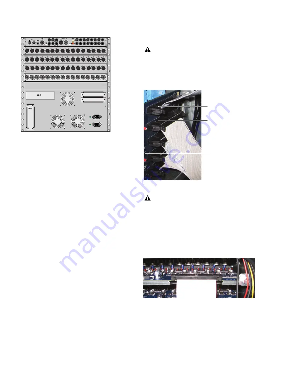
On the back panel of Mix Rack, locate output slot E and re-

move the card slot cover.

5  

Remove the card from its packing material. Hold the card by 

its edges.

6  

Gently slide the card into the output slot.

7  

When the card is seated in its slot, use the captive thumb-

screw to secure the card to Mix Rack’s chassis in the back of 
Mix Rack. 

8  

Secure the card to the front panel of Mix Rack using the cap-

tive thumbscrews you removed earlier.

9  

Find the Hub48 Board ribbon cable that corresponds to the 

output slot in which you have installed the card. The Hub48 
board’s five ribbon cables connect to the input and output 
cards

10  

Connect the ribbon cable to the card socket on the A016 

card. Make sure the pins on the socket are correctly aligned 
with the ribbon cable connector. Secure the connection by 
moving the retaining clips on each side of the socket connec-
tor inward. Check to make sure the ribbon cable is connected 
securely.


Mix Rack back panel

Output 
slot E

Do not remove or re-seat the ribbon cable connections on 
the Hub48 Board while the board is installed in the Mix 
Rack. This may cause excessive flexing of the Hub48 
Board. If necessary, disconnect the Hub48 and all Expan-
sion Card ribbon connections, and remove the entire assem-
bly from the rack prior to changing connections.

Detail of back of Mix Rack, the Hub48 Board, and the ribbon cables

Mix Rack contains 5 ribbon cables that connect to the Input 
and Output Cards. The top two ribbon cables connect to the 
output cards installed in output slots D and E.

A properly connected Expansion Card

Connects to card 

Connects to card
in Output Slot E

in Output Slot D

Hub48 Board

Summary of Contents for VENUE AO16

Page 1: ...Technical Support USA tel 650 731 6100 fax 650 731 6375 Product Information USA tel 650 731 6102 tel 800 333 2137 International Offices Visit the Digidesign Website for contact information Website www digidesign com VENUE AO16 Analog Output Card For VENUE Mix Rack and VENUE SC48 9321 61199 00 REV A 03 09 ...

Page 2: ...e following standards regulating interference and EMC FCC Part 15 Class B EN 55103 1 E3 EN 55103 2 E3 AS NZS 3548 Class B CISPR 22 Class B Radio and Television Interference This equipment has been tested and found to comply with the limits for a Class B digital device pursuant to Part 15 of the FCC Rules DECLARATION OF CONFORMITY We Digidesign 2001 Junipero Serra Boulevard Suite 200 Daly City CA 9...

Page 3: ...nents 1 AO16 Card Capabilities and Features 1 System Requirements 1 Conventions Used in This Guide 2 Chapter 2 Installing the AO16 Card 3 Installing an AO16 Card in Mix Rack 3 Installing an AO16 Card in SC48 5 Chapter 3 Specifications 7 Audio Specifications 7 ...

Page 4: ...AO16 Analog Output Card iv ...

Page 5: ...ation Card This guide AO16 Card Capabilities and Features The AO16 Card provides the following 16 channels of analog line level outputs via XLR 3 male connectors 24 dBu maximum output level System Requirements One of the following are required to use the AO16 Card with your installed and configured VENUE system A Mix Rack with an available output card slot or An SC48 console with an available outp...

Page 6: ...Pro Tools choose Save Session from the File menu Options System Config In the D Show software screen click Options to dis play the Options page then click the System Config tab Ctrl N Hold down the Control key and press the N key Ctrl click Hold down the Control key and click the mouse button User Tips are helpful hints for getting the most from your VENUE system Important Notices include informat...

Page 7: ...k has two available output card slots slots D and E AO16 Cards can be installed in either or both slots These in structions assume you already have an AO16 Card installed in slot D and that slot E is empty To install an AO16 Card 1 Shut down the VENUE system and turn off power to the Mix Rack 2 Disconnect all cables from Mix Rack 3 Remove Mix Rack s front panel cover by unscrewing its mounting scr...

Page 8: ... on the socket are correctly aligned with the ribbon cable connector Secure the connection by moving the retaining clips on each side of the socket connec tor inward Check to make sure the ribbon cable is connected securely Mix Rack back panel Output slot E Do not remove or re seat the ribbon cable connections on the Hub48 Board while the board is installed in the Mix Rack This may cause excessive...

Page 9: ...8 as well as any other audio cables that may get in your way 3 On the back panel of the SC48 locate output slot E 4 Remove the four screws holding the card slot cover in place You can use a flathead screwdriver to pry the cover away from the output slot after removing the screws Keep the screws nearby for securing the card to the SC48 5 Clip the cable tie to free the ribbon cable that is attached ...

Page 10: ...cables to the SC48 2 Turn on your SC48 3 Go to the Options page and click the Devices tab to view your system hardware status The newly installed card should be displayed 4 Go to the Patchbay page and click the Stage tab to verify that the output card outputs are available in the patchbay 5 In the standalone software click the Devices tab on the Op tions page You can right click the SC48 graphic t...

Page 11: ...h 150 Ohm source impedance and 600 Ohm load impedance unless otherwise specified 0 dBU 0 775Vrms AO16 Analog Line Outputs Parameter Specifications Limit Units Condition Comment Type Balanced XLR3 Male Impedance 50 Ohm Each leg to ground Maximum Output Level 24 max dBu D A Converter Latency 0 58 ms Fs 48kHz ...

Page 12: ...AO16 Expansion Card Guide 8 ...

Reviews: