Hybrid Inverter Users’ Manual
Page | 7
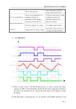
solar charger. Otherwise the battery life span will be shortened by overcharging.
Meanwhile, it is still in the bypass mode supplying electricity to the load.
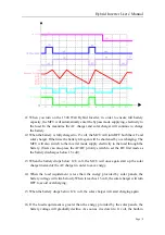
t3: Even if it is in the bypass mode, the battery voltage will gradually drop due to the
standby loss from the 1500 Watt Hybrid Inverter. Once the battery drops below 12.8
volt, it will be charged by the AC charger upon the charger current below 8A (e.g.
night time or cloudy days). Likewise, it will be charged by the solar charger above
8A.
t4: When the load requirement is less than the energy provided by the chargers, the
battery voltage will climb slowly. Once it reaches 15 volt, the MCU will shut off the
chargers and supply the electricity to the load.
t5: As the charger is OFF, the battery voltage will slowly fall between 13.2 volt and 15
volt (float charging). Once a power cut occurs, the MCU will automatically turn ON
the inverter mode (<15ms) to keep loads running.
t6: When the power returns, the MCU will switch to the bypass mode supply electricity
to the load. If the battery voltage drops to 12.8 volt, the MCU will once again start
charging.
t7: When the load requirement is less than the energy provided by the chargers, the
battery voltage will climb slowly. Once it reaches 15 volt, the MCU will shut off the
chargers and supply electricity to the load.
t8: When a power cut occurs, the MCU will automatically turn on the inverter mode
(<15ms) to keep loads running.
t9: Since the inverter mode is ON, the battery will be discharging rather quickly. As the
battery drops below 12.8 volt, the solar charger will be turned on again.
t10: As the battery voltage falls as low as 10 volt and the utility remains unavailabe, the
battery will be charged by only the solar charger. Then the battery will discharge
very fast since the inverter continues supplying power through it. The inverter
mode eventually shut down to prevent over discharging.
t11: When the battery voltage rises to 13.2 volt, the MCU will restart the inverter
supplying power to the load.
t12: If the solar charger current is more than 8A and the utility is not available at the
same time, the power to the battery is provided by the solar charger. As soon as the
battery reaches 15 volt again, the soalr charger will be turned OFF simultaneously.
8.
DC Power First

