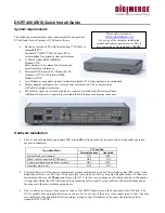
4. Finally, after all other connections are completed, connect the power supply cord (DC 12V 1.2A) to the power input
on the back of the unit.
Immediately after the power is supplied to the
DVS
unit, the board starts the internal self-test. Test progress is always shown
on the front LEDs. There are 2 LEDs:
POWER (yellow)
and
ACTIVE (green)
. The LEDs will behave in the manner as
described below during power up sequence:
Test (power-up) behavior of
DVS
unit.
1.
ACTIVE (green)
and
POWER (yellow)
turn on together, then
ACTIVE (green)
turns off.
2.
POWER (yellow)
during the whole test will indicate test progress step by step by turning off for a short time at the
beginning of each step 13 times.
3. When the test successfully passes,
POWER (yellow)
remains lit and the
ACTIVE (green)
starts blinking 2 times
per second (status is disconnected).
4. When the
DVS
detects a connection, the
ACTIVE (green)
light will blink at double the rate it blinks in the
disconnected state.
If these steps do not occur with your system, disconnect and reconnect the power and try again.
Software Installation
The Digimerge
DVS
client software can be easily installed on any desktop or notebook PC runnin g Windows 95,
Windows 98, Windows Me, Windows NT 4.0, Windows 2000 or Windows XP operating systems that is equipped with an
internal or external modem. The installation is done by simply double-clicking on the dm51xx.exe self-executable file (xx
here is the version number). The install script will then proceed and you should follow the prompts as indicated.
As a result, the Digimerge
DVS
application program (DM51App.exe) and the online help file will be installed automatically
on the PC. However, before you proceed with launching the Digimerge
DVS
software for the very first time, make sure that
the modem drivers and other software are correctly installed and functional.
Getting started with Digimerge DVS client program
After clicking on the Digimerge icon to launch the
DVS
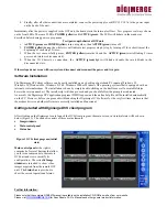
client program, the main screen, in its initial state will be shown
below (Figure 1). The window consists of three main elements:
•
Image windows
•
Main control panel
•
Status bar
Figure 1
DVS
client program (initial
state)
Main control panel
at the right is
comprised of several buttons that allow
you to issue commands to the remote
DVS
unit and view or modify its
configuration. The resizable
Image
windows
are intended to show video
images acquired from the remote
DVS
unit. The
Status bar
is provided to
show the current operational status.
Further Information:
Please note that the complete QDU0470 manual is available on the installation CD-ROM as well as from our website.
Please visit
WWW.DIGIMERGE.COM
for Spec Sheets, FAQ’s, Manuals and other general product information.
Status bar
Control panel
Image window


