background image

DG-GS1510PL User Manua

l

Page 28

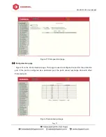
Figure 24 the MAC filtering configuration page

2

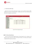
MAC filtering automatic conversion page

Figure 25 is the MAC filtering automatic conversion page. This page is used to achieve the port

MAC address auto-binding.

Figure 25 the MAC filtering automatic conversion page

Summary of Contents for DG-GS1510PL

Page 1: ...GS1510PL 8 PORT GIGABIT WEB MANAGED POE SWITCH WITH 2 GIGA SFP PORTS User Manual V1 0 2019 01 18 As our products undergo continuous development the specifications are subject to change without prior notice ...

Page 2: ...y be possible that information in this document is not up to date Please check with your local distributors for latest information No part of this document can be copied or reproduced in any form without written consent from the company Trademark DIGISOL TM is a trademark of DIGISOL Systems Ltd All other trademarks are the property of the respective manufacturers ...

Page 3: ...p switch installation 6 Desktop or Shelf Installation 6 Rack Installation 7 Third step Plugging in the AC Power Cord 7 Power failure 7 3 Getting Started 8 Management Option 8 Using Web based Management 8 Supported Web Browsers 8 Connecting to the Switch 8 Login Web based Management 9 1 WEB page Introduction 10 1 Logon dialog box 10 2 Page button introduction 11 3 Entry Field 11 4 Status Field 12 ...

Page 4: ...tion 32 7 ACL Configuraion 33 8 QoS Configuration 37 9 IP Basic Configuration 38 10 Certification Authorization Accounting AAA configuration 40 11 Spanning Tree Protocol configuration 44 12 IGMP SNOOPING configuration 47 13 GMRP configuration 49 14 EAPS configuration 51 15 RMON configuration 52 16 Cluster configuration 54 17 log management 57 18 PoE port configuration 58 ...

Page 5: ... its components network connections and technical specifications Terminology Usage In this guide the term Switch first letter capitalized refers to the Smart Switch and switch first letter lower case refers to other Ethernet switches Some technologies refer to terms switch bridge and switching hubs interchangeably and both are commonly accepted for Ethernet switches Note indicates important inform...

Page 6: ...e Power LED lights up when the Switch is connected to a power source Link Act LED The Link Act LED will flash which indicates a network link through the corresponding port Blinking indicates that the Switch is either sending or receiving data to the port PoE LED Green Indicates the PoE powered device PD is connected and the port supplies power successfully Light off Indicates no powered device PD ...

Page 7: ...kets 2pcs CD If any item is found missing or damaged please contact the local re seller for replacement Second step switch installation For safe switch installation and operation it is recommended that you Visually inspect the power cord to see that it is fully secured to the AC power connector Make sure that there is proper heat dissipation and adequate ventilation around the switch Do not place ...

Page 8: ...r and then plug in output terminal of the adapter into the DC IN socket on the back of the switch The AC power outlet should be grounded Warning Do not turn on the power switch before power cables are connected Power surge may cause damage to the Switch Warning The installation instructions clearly state that the ITE is to be connected only to PoE networks without routing to the outside plant Powe...

Page 9: ...eb based Management Using Web based Management After a successful physical installation you can configure the Switch monitor the network status and display statistics using a web browser Supported Web Browsers The embedded Web based Management currently supports the following web browsers Internet Explorer 6 or higher version Netscape 8 or higher version Mozilla Firefox 1 5 2 0 or higher version C...

Page 10: ...e x is a number between 1 254 and a subnet mask of 255 255 255 0 Open the web browser and enter 192 168 0 1 the factory default IP address in the address bar Then press Enter Enter the IP address in the web browser NOTE The switch s factory default IP address is 192 168 0 1 with a subnet mask of 255 255 255 0 To log in to the switch the IP address of your PC should be set in the same subnet as tha...

Page 11: ... the user enters the web page at the first time default IP address is 192 168 0 1 24 When the user fills out the correct user name and password then clicks the Enter button can log on to the switch Web server Passwords are case sensitive the anonymous user password can be a maximum of up to 16 characters while the multi user name and password can be set up to 11 characters Switch switch default us...

Page 12: ... this field user can access different rows in the table When you choose a line for the field it will display the corresponding information in the first line where you can also edit the information This line is also known as activities line When it is loaded for the first time it shows the field new activity line is empty If you want to add a new line you should select new from the drop down menu o...

Page 13: ...e state field is in the extreme right corner which displays the line status Since all row state changes are processed in house so the status field is read only Once the information is filed it will automatically go to active state and the the status will be active Figure 3 the web page of status field ...

Page 14: ...relevant parameters of system System descriptor ID displays system in the network identity management The system version number displays the current software version number of switches The system start up time displays switch s time from switch start to the present time The system name is the switch s system name in the network the user can modify the system name The system location is the switch ...

Page 15: ...uration page this page displays serial baud rate and other related information When the host through the serial port terminals such as Windows Hyper Terminal connects to switches then COM port configuration must be consistent with this page information Figure 10 Serial port information page Figure6 Serial port information page ...

Page 16: ... the web page with a new anonymous user password Figure 7 user s management page 4 Security Management Page Figure 8 is Security management configuration page Using this configuration the administrator can control network management services like TELNET WEB and SNMP You can switch on enable or off disable this service Also these services can be mapped with standards IP ACL group and the implementa...

Page 17: ... configuration of the switch on this page Save button is to store the current system configuration in the configuration file Because the storage operation requires erasing writing into the FLASH memory it may take up some time When the user was configures the switch and restarts it after saving then configurations are not lost Figure 9 the current configuration page ...

Page 18: ...tion file to the PC Click to download button will pop up a dialog box users select Save and save the configuration file directory path Download the configuration file names are as switch cfg Figure10 Configuration file page 7 File upload page Figure 11 is a file upload page through this page a user can upload a configuration file and mapping files to the switch Click the Browse button to select th...

Page 19: ...Page 8 System reset page Figure 12 is system reset page Through this page users can restart the switch When you click on Restart button it will pop up a dialog box that prompts the user to determine whether to restart the switch Figure12 System reset page ...

Page 20: ...ort status is up The drop down menu can select down to disable the port Users can also choose to set the speed from drop down menu to set the speed of the port On this page the user can also view the port s other basic information Figure 13 port configuration and port display page 2 Port Statistics Page Figure 14 is the port statistics information page To view a particular port users need to selec...

Page 21: ... Manual Page 20 Figure 14 Port Statistics Page 3 Flow control page Figure 15 is the flow control page Users can enable and disable each port s send and receive flow control through this page Figure 15 Flow control page ...

Page 22: ...ect the relevant ports Bandwidth control of the send data packets is used to configure and display the bandwidth control it If the port is not configured for bandwidth control it is shown as off Cancel button is used to cancel the corresponding data packet to send bandwidth control Receiving data packets is used to configure and display the bandwidth control of receive data packets control the ran...

Page 23: ...age 6 Port protection page Figure 18 is the Port protection page This page is used to configure the port for the protection port If the port is configured as a protected port the ports cannot exchange data with other Protected port Figure 18 protected port page ...

Page 24: ...default value is 8191 also is the maximum that the port is not configured the restrict learning Figure 19 Port Learning restrain page 8 Port Trunking configuration page Figure 20 is the port trunking configuration page This page allows the user to configure the port trunking This page consists of four parts Port trunking ID selection Port trunking method selection Configurable ports and group memb...

Page 25: ...ort to remove a port group member ports in the trunking port selected click on non member port key To delete the entire TRUNK group then click the Delete trunk group button In page configuring process if at least one Trunk has been established then polymerization settings can take effect configured Trunking method is also applied to all on the Trunk groups in that already exist on the Trunk can ad...

Page 26: ...r port firstly configured mirroring port from monitor ports mirror ports can only have one and then select the mirror port from the configurable port select the monitor direction and press the application key to entry into force the results is displayed in the mirrored configuration information When you choose the RECEIVE direction of monitoring received data packets will be monitored TRANSMIT sen...

Page 27: ... the port and MAC address binding MAC entries on the page is used to enter the MAC address binding VLAN ID entry is used to enter the MAC address of VLAN Figure 22 the MAC binding configuration page 2 MAC binding automatic conversion page Figure 23 is the MAC binding automatic conversion page This page is used to achieve the port MAC address auto binding ...

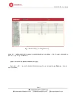
Page 28: ... filtering 1 MAC filtering configuration page Figure 24 is the MAC filtering configuration page This page is used to configure MAC address filtering on the ports MAC entries on the page is used to enter the MAC address filtering VLAN ID entry is used to enter the MAC address affiliated VLAN ...

Page 29: ...MAC filtering configuration page 2 MAC filtering automatic conversion page Figure 25 is the MAC filtering automatic conversion page This page is used to achieve the port MAC address auto binding Figure 25 the MAC filtering automatic conversion page ...
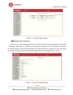
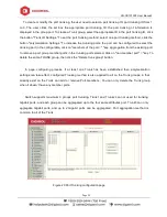
Page 30: ...information including the VID state and port members Select VLAN from the drop down VID shows the port information of the Port VLAN members A port may not be a member of VLAN which can be VLAN tagged or untagged members the meanings of characters pls see the following info t Tagged the port is the VLAN tagged member u Untagged the port is the VLAN untagged member Figure 26 VLAN information page ...

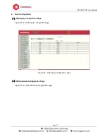
Page 31: ...s generated depend on VLAN ID and can not be modified Click Apply button then the list box displays the user created VLAN s VID and VLAN name Switch by default has VLAN1 and VLAN1 can not be deleted If you want to delete a VLAN the user need to click the appropriate VLAN of the list box The VLAN will be displayed in the activity line click the Remove Delete key to delete the VLAN the same time Fig...

Page 32: ...s VLAN1 VLAN Port shows the results of VLAN port configuration p indicates that the port VLAN is the default VLAN t that the port is a VLAN tag members u that the port is not tagged VLAN member When you remove VLAN the user from the list select the VLAN can be multiple choice Button default VLAN is used to configure port to new default VLAN Button tagged Configured port is designated as a tagged m...

Page 33: ...d to configure a read write permissions to the shared body Figure 29 a shared body of SNMP configuration page 2 TRAP target configuration page Figure 30 is the TRAP target configuration page that allows users to configure the workstation to receive TRAP messages as well as the IP address of TRAP protocol packets of some of the parameters In the configuration entry the name used to enter the TRAP n...

Page 34: ...CL configuration page Figure 31 is the IP standard ACL configuration page Users build ACL standard IP access list using this page User can select a ACL group number in the group to create one or more rules A rule can match only the source IP address field with mask Figure 31 the IP standard ACL configuration page ...

Page 35: ...rules each rule must have a filter mode allow or deny The user to create a rule in the group the system will automatically give a rule number 2 IP Extended ACL configuration page Figure 32 is the IP extended ACL configuration page The extended IP group is an extension of the standard IP rules Control the packet forwarding via source IP Destination IP IP protocol type and service port Figure 32 the...

Page 36: ...an be the IP packet source and destination MAC address and source and destination IP address control Figure 33 the MAC IP ACL configuration page 4 MAC ARP ACL configuration page Figure 34 is the MAC ARP ACL configuration page ARP group can be the type of the operation of the ARP packet the sender MAC and the sender IP control ...

Page 37: ...Page 36 Figure 34 the IP Extended ACL configuration page 5 ACL information page Figure 35 is the ACL information page which displays the current ACL rules configured in all the information Figure 35 is the ACL information page ...

Page 38: ...l Page 37 8 QoS Configuration 1 QoS Apply Configuration Page Figure 36 is a QoS Apply configuration page Figure 36 QoS Apply configuration page 2 QoS Schedule Configuration Page Figure 37 is a QoS Schedule configuration page ...

Page 39: ...LAN Interface Configuration Page Figure 38 is a VLAN interface configuration page Users can configure the VLAN interface through this page delete VLAN interfaces configure the interface IP address remove the interface IP address and view interface information Figure 38 VLAN interface configuration page ...

Page 40: ... page delete ARP entries and revise the dynamic ARP table entry to a static ARP table entry When a user configures a static ARP entry they need to enter the IP address and MAC address MAC address must be a unicast MAC address and then click Add button When a user delete an ARP entry you can choose to delete an IP ARP table entry remove a segment of the ARP table entry delete all of the ARP table e...

Page 41: ...n 1 Be sure to set the Radius server s IP address before do the authentication and accounting in this field 2 Optional Radius server IP address if there is spare Radius server 3 Authentication UDP port the default value is 1812 the user generally do not need to modify this field 4 Accounting enable when you do authentication and accounting in general to start charging 5 Accounting UDP port the def...

Page 42: ...on and accounting must be to start 802 1x protocol 2 To adopt a common authentication method or the expansion of authentication 3 Whether to open re authentication function the default is not open Open the re authentication feature will make users more reliable when using the authentication and accounting but it will slightly increase the network traffic 4 Setting re certification time interval on...

Page 43: ...fication passed then examine the client s regular flow of packets Figure 42 the 802 1x configuration page 3 802 1x port configuration page Figure 43 is the 802 1x port configuration page The user through this page can configure the 802 1x port mode 802 1x port model includes four types N A State Auto state Force authorized state and Force unauthorized state When a port needs to do 802 1x Authentic...

Page 44: ...thentication port access the default maximum host number is 100 the user can modify this field the biggest support to the 100 4 802 1x user authentication information page Figure 44 is a 802 1x user authentication information page the user can see through this page all users state information ...

Page 45: ...dge Enable BPDU filtering function on the port in the portfast bpdu filter default state Enable BPDU guard function on the port in the portfast bpdu guard default state Configure the forwarding delay Configure the interval for sending MSTP Hello packets The errdisable mechanism is started When a port starts a BPDU guard receives a BPDU it starts the error disable timer Error disable restarts this ...

Page 46: ... to the forwarding state bypassing the listening and learning states Open the BPDU filter on the selected port Enable BPDU guard on the selected port Enable the root guard function and do not accept BPDU packets with a higher priority than the bridge Specify the switch as the root switch Configure the connection type point to point The type of connection is point to point allowing fast transition ...

Page 47: ...Manual Page 46 Configure the cist path cost Range 1 200000000 The default is 20000000 Lower path costs are more likely to be roots Configure the type of protocol packets to be sent Figure 46 MSTP Port Configuration Page ...

Page 48: ...STP configuration information page in this page you can view some MSTP related information Figure 47 MSTP Configuration Information page 12 IGMP SNOOPING configuration 1 IGMP SNOOPING configuration page Figure 48 is the IGMP SNOOPING configuration page this page you can start IGMP SNOOPING ...

Page 49: ...48 Figure 48 IGMP SNOOPING configuration page 2 IGMP SNOOPING information page Figure 49 is the IGMP SNOOPING information page which allows users to view some information about IGMP SNOOPING Figure 49 IGMP SNOOPING Information page ...

Page 50: ... Figure 50 shows the GMRP global configuration page Users can enable GMRP through this page Figure 50 GMRP Global Configuration Page 2 GMRP port configuration page Figure 51 shows the GMRP port configuration page You can use this page to enable the GMRP port and view the port information ...

Page 51: ...l Page 50 Figure 51 GMRP Port Configuration Page 3 GMRP state machine page Figure 52 is the GMRP state machine page Users can view the GMRP state machine information through this page Figure 52 is the GMRP state machine page ...

Page 52: ...mode of an EAPS Domain Configure Primary Port of EAPS Domain Configure Secondary Port of EAPS Domain Configure a control VLAN for EAPS Domain Add one or more protected VLANs of the EAPS Domain Configure an EAPS Domain to periodically send HEALTH packets Hello timer must be less than fail time Set the fail period timer of one EAPS domain to expire Enable or disable compatibility with Extreme device...

Page 53: ...RMON statistics group configuration page You can use this page to configure the RMON statistics group Select a port from the drop down list to view configure the RMON statistics group configuration for this port When not configured the index number is 0 fill in the correct index number range 1 to 100 the owner is optional you can configure RMON statistics group for the port The statistics table sh...

Page 54: ... When not configured the index number is 0 fill in the correct index number range is 1 to 100 interval request Buckets the owner is optional you can configure the RMON history group for the port Interval refers to the time interval in seconds that the data is collected The range is 1 3600 The bucket is the allocated storage size and it indicates how many records are stored The range is 1 100 The s...

Page 55: ... to the index number of the RMON event group and must be configured in advance Figure 57 RMON Event Group Configuration Page 16 Cluster configuration 1 NDP configuration page Figure 58 shows the NDP configuration page You can use this page to configure NDP The configurable information includes selecting the port enabling the NDP function of the port enabling the global NDP function the interval fo...

Page 56: ... select the port as required and enable the NTDP function on the port For NTDP to operate normally both global and port NTDP must be enabled The range of topology collection is configured The valid range is 1 6 In the default configuration the maximum number of hops from the most distant device to the topology collection device is 3 Set the interval for collecting the topology collection The valid...

Page 57: ...iguration is vlan1 Configure a private IP address range for member devices in the cluster The valid range of ip addresses is 0 0 0 0 to 255 255 255 255 The valid range of the mask length is 0 to 32 Set the interval for sending handshake packets The valid range is 1 255 seconds The default is 10 seconds Configure the device s effective retention time The valid range is 1 255 seconds and the default...

Page 58: ...l Page 57 Figure 50 Cluster Configuration Page 17 log management 1 Log information page Figure 61 is the Log information page Users can enable and view various log information through this page Figure 61 Log Information Page ...

Page 59: ...ation ALL output all log information 18 PoE port Configuration Page Figure 62 is the PoE port configuration PoE display page Users can enable or disable the port s PoE function to the page or View all ports of PoE information Information can be seen in the following tables 1 Status Enable means PoE function is available Disable means PoE function is disabled 2 Operation Displays the PoE ports ON o...

Page 60: ...DG GS1510PL User Manual Page 59 ...

Reviews: