Chapter 2 – Specifications
GLC2300 Series User Manual
2–10
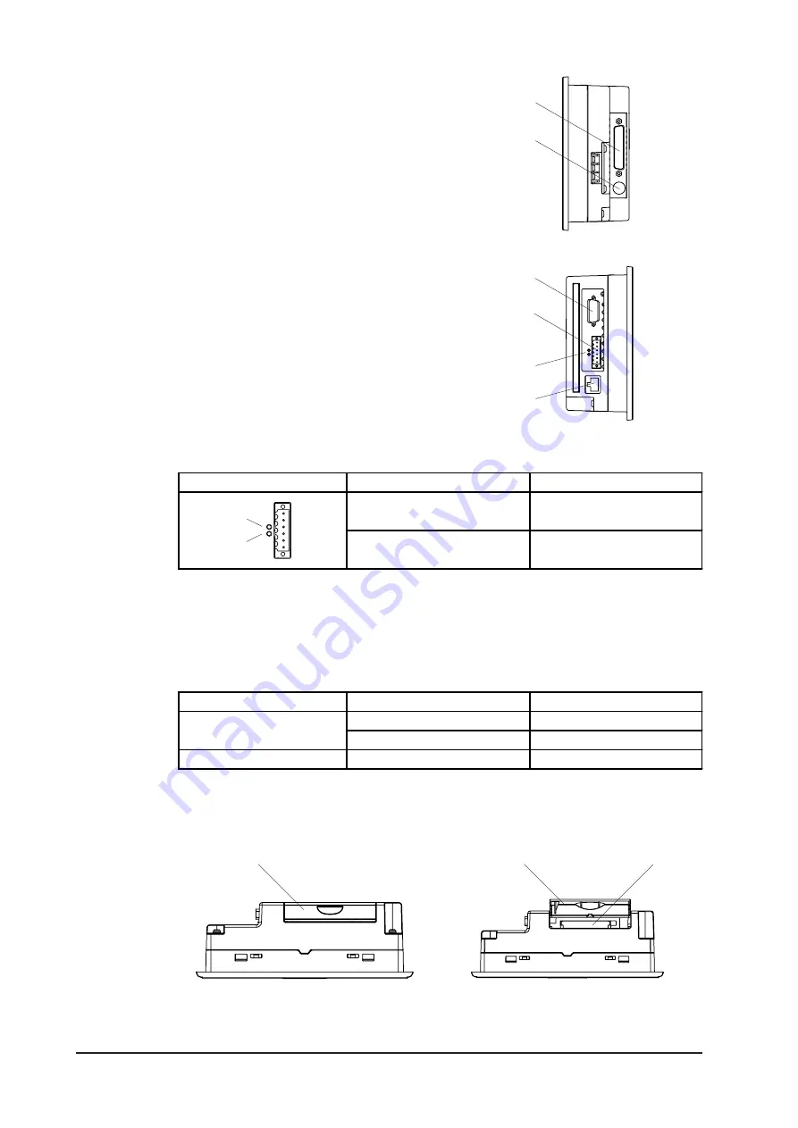
G: Serial Interface (COM1)
RS-232C/422 Interface (Dsub 25-Pin).
Connects to a host (device/PLC) or a tem-
perature controller.
H: Tool Connector (TOOL)
Connects to Transfer Cable, Bar Code
Reader, Serial Printer.
I:
Expansion Serial Interface (COM2)
RS-232C Interface (Dsub 9-Pin).
J: Screw Lock Terminal Block (Flex
Network)
Flex Network Interface.
K: Flex Network Interface
Flex Network I/F status LED will turn ON
or flash, according to the unit’s status.
J
G
K
L
I
H
Right
Left
LED
Status
Description
a: RUN (Green)
Turns on when
Communication is enabled.
b: ERR (Red)
Turns on when failure occurs
in connected I/O Unit.
a
b
L: Ethernet Interface (10BASE-T)
Used for Ethernet (10BASE-T).
The LED will change (turn ON, blink)
according to the GLC unit’s status.
M: CF Card Cover
N: CF Card Slot
Status LED
Display
Description
ON
Power ON
Flash
Send/Receive
Green
ON
Link
Orange
Bottom
CF Cover Open
M
M
N


