3–7
Chapter 3 – Installation and Wiring
GLC2300 Series User Manual
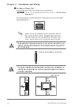
To connect the power supply lines:
1. Make sure the GLC unit’s power cord is not plugged in to the power supply.
2. Remove the Terminal Strip’s clear plastic cover.
3. Remove the terminal attachment screws from the three (3) middle terminals, position
the Ring Terminals on the correct electrode, and reattach the screws.
See
3.2.2 – “Connecting the Power Supply.”
•
Be sure that each Ring Terminal is connected to the correct termi-
nal.
•
Use a torque of only 0.5 to 0.6 N•m to tighten the terminal attachment
screws.
4. Reattach the Terminal Strip’s clear plastic cover.
3.2.2
Connecting the Power Supply
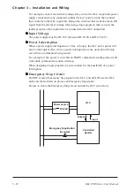
• When supplying power to the GLC unit,
separate the input/output and operation
unit lines (see Diagram 1).
• To increase the noise resistance quality
of the power cord, twist each power
wire before attaching the Ring Terminal.
• The power supply cord must not be
bundled or positioned close to main
circuit lines (high voltage, high current),
or input/output signal lines (see Diagram
2).
• Connect a lightning surge absorber (see
Diagram 3) to deal with power surges.
• To avoid excess noise, make the power
cord as short as possible.
•
Ground the surge absorber
(E1) separately from the GLC
unit (E2).
•
Select a surge absorber with
a maximum circuit voltage that
is greater than that of the
power supply’s peak voltage.
Main
power
I/O
device
Main circuit power
I/O
device
I/O
device
Operation
unit
Input/
Output
power
Lightning
surge
absorber
Input/
Output
power
Main
power
GLC
power
GLC
power
GLC unit
GLC unit
GLC unit
Dia. 1
Dia. 2
Dia. 3


