Operation
3.1.3 Battery Unit Controls
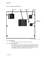
The battery unit circuit breaker (see Figure 3–2), located on the rear panel of
the battery unit, must be ON before the UPS can charge the batteries or receive
battery back-up power. It opens and closes the circuit between the battery unit
and the battery circuit breaker on the UPS front panel.
When the battery unit circuit breaker is ON, battery voltage is applied to the
battery circuit breaker on the UPS front panel. When the battery unit circuit
breaker is tripped or turned OFF, all battery voltage is removed from the UPS.
3.2 Output Distribution
Output distribution for the 2T-HA10F-CD UPS is provided through a distribution
panel located on the rear panel of the UPS (see Figure 3–2). This distribution
panel contains six NEMA 6-15R (15 A, 208 V) receptacles.
3.3 Emergency Shutdown Plug
The 2T-HA10F-CD UPS is shipped with an emergency shutdown plug installed in
the emergency shutdown jack on the rear of the UPS (see Figure 3–2).
The UPS will not operate if the emergency shutdown plug is not installed or if
the circuit between the terminals of the emergency shutdown plug is broken.
Pulling the emergency shutdown plug out of the emergency shutdown jack shuts
down the UPS by tripping the ac input circuit breaker and the battery circuit
breaker on the front panel.
The emergency shutdown plug also provides the connections for a Remote
Emergency Power Off (REPO) device. The REPO device must have contacts that
are normally closed and rated for a minimum of 80 V and 10 mA.
Use the following procedure to connect a REPO device to the emergency shutdown
plug:
1. Turn the UPS OFF.
2. Remove the emergency shutdown plug from the emergency shutdown jack on
the back of the UPS (see Figure 3–2).
3. Disassemble the emergency shutdown plug and remove the metal strip that
connects the plug’s two terminals to each other.
4. Route the wire from the REPO device through the rubber grommet on the
back of the system cabinet.
5. Connect one wire per terminal from the REPO device to the plug’s terminals.
6. Reassemble the emergency shutdown plug and plug it into the emergency
shutdown jack on the back of the UPS.
3–6 Operation

