Operation
Typically, the UPS logic trips the battery circuit breaker on the front panel if
there is a failure in the UPS, or if the battery system needs protection. Tripping
the battery circuit breaker on the front panel causes the UPS to automatically
transfer the load to the bypass line. The UPS can also be forced to transfer the
load to the bypass line, by manually turning the battery circuit breaker on the
front panel to the OFF position.
CAUTION
If the UPS is transferred from Normal mode to Bypass mode
when ac input is available and the loads are ON, the loads may
be dropped because of a momentary power interruption during
transfer.
Use the following procedure to manually transfer the UPS from Normal to Bypass
mode.
1. Ensure that the green status light labeled "Normal" is lit to indicate that the
UPS is in Normal mode.
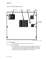
2. Place the battery circuit breaker, located on the front panel of the UPS (see
Figure 3–1), to the OFF position.
The yellow "Bypass" status light on the UPS front panel should light to
indicate that the UPS is operating in Bypass mode.
NOTE
If the UPS was not forced into Bypass mode by turning OFF the
battery circuit breaker on the front panel, the UPS probably
transferred into Bypass mode automatically because of an
abnormal condition. If the UPS automatically transferred to
Bypass mode, correct the condition that caused the transfer
before transferring the UPS back to Normal mode.
3.4.4 Manual Transfer from Bypass to Normal Mode
Use the following procedure to manually transfer the UPS from Bypass to Normal
mode.
1. Ensure that the yellow status light labeled "Bypass" is lit to indicate that the
UPS is in Bypass mode.
2. Place the battery circuit breaker, located on the front panel of the UPS (see
Figure 3–1), to the ON position.
The green "Normal" status light on the UPS front panel should light to
indicate that the UPS is operating in Normal mode.
Operation 3–9


