background image

3

Assembling the Slides

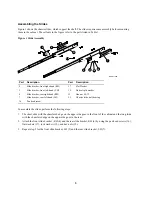
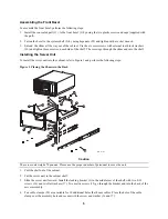
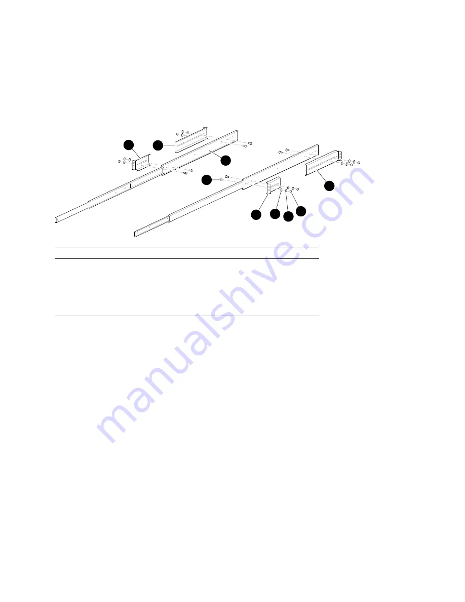
Figure 1 shows the chassis slides, which support the shelf. The slides require some assembly before mounting
them in the cabinet. The callouts in the figure refer to the parts listed in Table 1.

Figure 1  Slide Assembly

MLO-011564

4

5

6

7

16

17

18

19

21

Part

Description

Part

Description

4

Slide bracket, front right-hand (RH)

17

Flat Washer

5

Slide bracket, front left-hand  (LH)

18

Helical split washer

6

Slide bracket, rear right-hand (RH)

19

Hex nut #8-32

7

Slide bracket, rear left-hand (LH)

21

Chassis slide, ball bearing

16

Pan head screw

To assemble the slides, perform the following steps:

1.  The short slide with the chamfered edge on the upper side goes in the front of the cabinet and the long slide

with the chamfered edge on the upper side goes in the rear.

2.  Attach the front slide bracket , RH (4) and the rear slide bracket, RH (6) by using the pan head screws (16),

flat washers (17), lock washers (18), and hex nuts (19).

3.  Repeat step 2 for the front slide bracket, LH (5) and the rear slide bracket, LH (7).

Summary of Contents for AlphaStation 600

Page 1: ...Installation Table 1 lists the parts of your AlphaServer 1000 AlphaServer 1000A AlphaStation 600 rackmount kit Ensure that you have all the parts before you assemble the rackmount kit Table 1 Parts Li...

Page 2: ...sher lock 90 07651 00 8 36 Pan head sems screw 8 32 90 09312 00 6 Installation Requirements System installation requires the following A cabinet with an internal rail dimension range of 24 25 inches t...

Page 3: ...al split washer 6 Slide bracket rear right hand RH 19 Hex nut 8 32 7 Slide bracket rear left hand LH 21 Chassis slide ball bearing 16 Pan head screw To assemble the slides perform the following steps...

Page 4: ...o the Cabinet To install the slides into the cabinet perform the following steps 1 Before installing the slides into the cabinet select the cabinet location for your server system The server needs 10...

Page 5: ...nto the cabinet refer to Figure 3 and perform the following steps Figure 3 Placing the Chassis in the Rack 1 11 2 22 36 16 17 20 12 16 17 3 15 8 9 26 13 34 10 15 MLO 011566 14 35 Caution The server un...

Page 6: ...sliding of other latches and stabilizer brackets to accommodate the new configuration 7 Place the nut plate 31 behind the RETMA rail and install and tighten the two 10 32 truss head screws 33 provided...

Page 7: ...place for shipping or moving perform these steps 1 Face the rear of the cabinet and place the wide end of the shipping bracket 8 to the left over two holes on the left side of the shelf 2 Tighten two...

Page 8: ...Help...

Reviews: