background image

Removing and Replacing Field Replaceable Units

3.8 Removing an RF31T/RF35/RF36 Disk Drive

4. Keep the mounting bracket and the four screws in a safe place because you

must use the same bracket and screws to install the replacement RF-series

drive.

3.8.2 Setting the DSSI ID

In a BA42B-based VAX 4000 system, each DSSI device must have a unique

DSSI ID number. When installing RF31T/RF35/RF36 disk drive options, the

DSSI ID must be set to an ID that is not used by any other DSSI device in the

system. (Refer to the

VAX 4000 Models 100, 100A, 105A KA52/53 CPU System

Maintenance

manual for further information.)

To set the DSSI ID on RF31T/RF35/RF36 disk drive options, follow these steps:
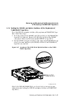
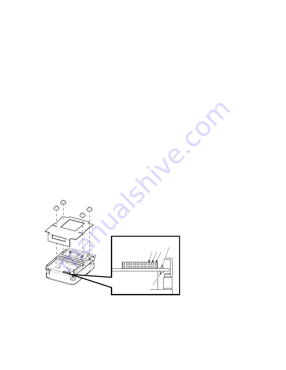
1. Locate the DSSI ID jumper on the disk drive (see Figure 3–24).

Table 3–2 shows the DSSI ID jumper combinations.

Figure 3–24 Sample RF31T/RF35/RF36 Disk Drive Option with Mounting

Brackets

Pin

1

3

5

2

19

20

Fault LED

Busy LED

LJ-02126-TI0

Removing and Replacing Field Replaceable Units 3–35

Summary of Contents for BA42B

Page 1: ...Order Number EK 472AB MG B01 August 1994 This manual provides reference installation and maintenance information for the BA42B Enclosure used with the VAX 4000 Model 100 100A 105A systems Digital Equipment Corporation Maynard Massachusetts ...

Page 2: ...rdance with the description Digital Equipment Corporation 1994 All Rights Reserved The postpaid Reader s Comments forms at the end of this document request your critical evaluation to assist in preparing future documentation The following are trademarks of Digital Equipment Corporation DEC Digital MicroVAX OpenVMS Q bus ThinWire TK VAX VAX DOCUMENT VT and the DIGITAL logo All other trademarks and ...

Page 3: ...uipment 2 2 2 1 3 Operating Environment 2 3 2 1 4 Electrostatic Discharge 2 3 2 1 5 Heat Dissipation 2 3 2 1 6 Temperature Humidity and Altitude Ranges 2 4 2 1 7 Electrical Requirements 2 4 2 2 Unpacking the System 2 5 2 3 Installing the BA42B System 2 7 2 3 1 Installing a BA42B Based VAX 4000 Model 100 2 7 2 3 1 1 Identifying the Ports and Connectors on the System 2 7 2 3 1 2 Connecting the Conso...

Page 4: ... Board 3 14 3 4 2 Separating the RX26 Diskette Drive from the Mounting Bracket 3 15 3 4 3 Setting the SCSI ID on the Replacement RX26 FDI SCSI Board 3 16 3 5 Removing a TZ30 Tape Drive 3 19 3 5 1 Separating the TZ30 Tape Drive from the Mounting Bracket 3 21 3 5 2 Setting the SCSI ID on the Replacement TZ30 Tape Drive 3 22 3 6 Removing a TZK10 TZK11 Tape Drive 3 23 3 6 1 Separating the TZK10 TZK11 ...

Page 5: ...14 Removing the DSSI Daughter Board 3 55 3 14 1 Changing the DSSI ID 3 58 3 15 Removing the DSW42 Synchronous Communications Option 3 60 3 15 1 Removing the DSW42 Logic Board 3 60 3 15 2 Removing the DSW42 Input Output Cable 3 61 3 15 3 Removing the DSW42 Input Output Module 3 62 3 16 Removing the DHW42 Asynchronous Communications Option 3 64 3 16 1 Removing the DHW42 Logic Board 3 64 3 16 2 Remov...

Page 6: ...ombinations in the BA42B Enclosure 1 18 2 1 BA42B Dimensions 2 2 2 2 System Unit and Accessory Tray Contents 2 6 2 3 Connecting the Console Terminal 2 9 2 4 Connecting the ThinWire Terminator to the System 2 11 2 5 Connecting the Standard Ethernet Loopback Connector to the System 2 12 2 6 Connecting the SCSI Terminator 2 13 2 7 Connecting the DSSI Terminator 2 14 2 8 Connecting the Power Cord 2 15...

Page 7: ... 13 Removing a TZ30 Tape Drive 3 20 3 14 Separating the Mounting Bracket from the TZ30 Tape Drive 3 21 3 15 TZ30 SCSI ID Switch Locations 3 22 3 16 Removing the TZK10 TZK11 Tape Drive 3 24 3 17 Separating the Mounting Bracket from the TZK10 TZK11 Tape Drive 3 25 3 18 Locations of the SCSI ID Jumper Wires on the TZK10 TZK11 Tape Drive 3 27 3 19 Removing the TLZ06 TLZ07 Tape Drive 3 29 3 20 Separati...

Page 8: ...Removing the DSW42 Input Output Cable 3 62 3 40 Removing the DSW42 Input Output Module 3 63 3 41 Removing the DHW42 Logic Board 3 65 3 42 Removing the DHW42 Input Output Cable 3 66 3 43 Removing the DHW42 Input Output Module 3 67 3 44 Disconnecting the Cables from the CPU Module 3 69 3 45 Removing the CPU Module 3 71 3 46 Removing the Power Supply 3 74 A 1 Pin Specifications for the Ports on the B...

Page 9: ...ations for the Eight Data and 16 Data Line Options A 3 A 2 Asynchronous Port A and Port B Pin Specifications for the Eight Modem Control Line Option A 4 A 3 Pin Specifications for Synchronous Port 0 and Port 1 A 6 A 4 Pin Specifications for the External SCSI Connector A 9 C 1 Recommended Spare Parts C 1 ix ...

Page 10: ......

Page 11: ...ve a self maintenance agreement with Digital Equipment Corporation Users of this manual must have experience in replacing hardware components Structure of This Manual This manual is divided into three chapters three appendixes a glossary and an index Chapter 1 provides an overview of the system enclosure and describes the controls mass storage areas and capacity signal distribution power distribut...

Page 12: ... Appendix A gives the pin specifications for the ports on the back of the system unit Appendix B gives a list of the related documents Appendix C gives a list of recommended spare parts xii ...

Page 13: ...tic characters italic type Italic type emphasizes important information indicates variables and indicates the complete titles of manuals nn nnn nnn nn A space character separates groups of 3 digits in numerals with 5 or more digits For example 10 000 equals ten thousand n nn A period in numerals signals the decimal point indicator For example 1 75 equals one and three fourths Note A note contains ...

Page 14: ......

Page 15: ...BA42B Enclosure houses the system unit of the VAX 4000 Model 100 100A 105A systems It is a desktop style enclosure see Figure 1 1 Note The VAX 4000 Models 100A 105A can be distinguished from the Model 100 by the protruding connector panel see Section 1 2 The illustrations in this manual will show different models as examples Where the functionality differs it is called to the reader s attention an...

Page 16: ...rage devices These mass storage devices are mounted on two drive mounting shelves The upper drive mounting shelf can contain one two or three DSSI drives The lower drive mounting shelf can contain one or two SCSI devices that is CD ROM drives or removable media devices See Section 1 5 3 for information about mass storage device combinations and orientation 1 2 Enclosure Description ...

Page 17: ...A42B Enclosure Figure 1 2 shows the common ports and connectors in VAX 4000 BA42B based systems Figure 1 3 and Figure 1 4 show differences between the VAX 4000 Model 100 and the VAX 4000 Models 100A and 105A respectively Table 1 1 describes the functions of the controls indicators ports and connectors in all VAX 4000 BA42B based systems Enclosure Description 1 3 ...

Page 18: ...ll Models 0 A B 1 0 On Off Switch ac Power Socket Synchronous Communications Ports 0 1 Asynchronous Communications Ports A B MMJ Ports 0 1 3 Asynchronous Modem Control Port 2 Halt Push Button Break Enable Switch Break Enable LED LED Display Standard Ethernet Port Ethernet Switch ThinWire Ethernet Port Power OK Indicator POK MLO 012383 1 4 Enclosure Description ...

Page 19: ...osure Description 1 2 Controls Indicators Ports and Connectors Figure 1 3 Ports and Connectors Unique to the VAX 4000 Model 100 0 A B 1 0 SCSI Port DSSI Port MLO 012385 Q Bus Ports Enclosure Description 1 5 ...

Page 20: ...n 1 2 Controls Indicators Ports and Connectors Figure 1 4 Ports and Connectors Unique to the VAX 4000 Model 100A 105A 1 3 2 MLO 012384 3 1 2 2 4 DSSI port Q bus ports Optional DSSI ports SCSI port 1 6 Enclosure Description ...

Page 21: ...compatible asynchronous ports Eight EIA 232 compatible modem ports MMJ3 port 0 DEC423 compatible asynchronous port This port is the primary console port MMJ port 1 DEC423 compatible asynchronous port MMJ port 3 DEC423 compatible asynchronous port This port functions as an alternate console port when the break enable switch is set in the up position when you turn on the system unit Asynchronous mod...

Page 22: ... follows On MMJ port 3 functions as a console port Off MMJ port 3 functions as a normal communications port LED display A set of eight LEDs that provide power up and self test diagnostic code information This is useful for fault diagnosis when the console terminal is not functioning Standard Ethernet port A port that allows you to connect the system to a standard Ethernet network Ethernet switch A...

Page 23: ...al fans that cool the unit while it operates Table 1 2 gives the current specifications of the dc circuits Table 1 2 Power Supply dc Outputs Voltage dc Output Current Range in Amperes dc Minimum Maximum 5 1 3 8 15 0 12 1 0 18 7 1 12 0 0 3 1 0 9 0 0 0 0 2 3 3 0 0 3 5 The power supply 30 35042 01 has the following output connectors A flying lead connector that provides the dc power to the central pr...

Page 24: ...379 TZK10 11 or RRD42 42 or RX26 or TZ30 TZK10 11 or TZ30 or RX26 or RRD42 43 Appendix A provides information on the pin specifications for the connectors The CPU module is the main source for signal distribution in a BA42B Enclosure system The SCSI and DSSI cables are connected to the CPU module Each of the other connectors on the cables has a pull tab Use the pull tab to disconnect the cable fro...

Page 25: ...Internal SCSI Power Supply MLO 012380 External Q bus 17 03545 01 Internal DSSI DSSI Cable 17 03544 01 1 4 Air Circulation The power supply 30 35042 01 contains two fans These fans provide the air circulation for the enclosure The air intake is on the right side of the BA42B Enclosure when viewed from the front and the air exhaust is on the left side A typical value of airflow is 0 0104 cubic meter...

Page 26: ...ry Configurations In the VAX 4000 100 100A 105A the basic system memory is 16 MB or 64 MB This memory is contained on two sets of MS44L BC or MS44 DC modules installed on the KA52 KA53 CPU module You can expand the system memory in 16 MB or 32 MB increments by adding MS44L BC or MS44 DC memory options An MS44L BC memory option consists of four MS44L AA 4 MB memory modules An MS44 DC memory option ...

Page 27: ...B MLO 009828 Note Both MS44 DC four MS44 CA SIMMs and MS44L BC four MS44L AA SIMMs must be installed entirely in either the 1 bank or the 0 bank of connectors do not mix them in banks Figure 1 8 shows the banks of slots as they are viewed from the front of the system The 1 set of banks is shaded for identification Enclosure Description 1 13 ...

Page 28: ... Configuration Guidelines Figure 1 8 Identifying Appropriate Banks of SIMM Connectors 1G 0C 1E 0A 1H 0D 1F 0B 2 1 6 5 4 3 8 7 MLO 012342 Bank 1G Bank 0C Bank 1H Bank 0D Bank 1E Bank 0A Bank 1F Bank 0B 1 14 Enclosure Description ...

Page 29: ...ronous lines 1This option is supplied with two external cables that support the EIA 232 V 24 interface The DSW42 AA option also supports the communications interfaces listed in Table 1 4 but you must order the external cable separately Table 1 4 DSW42 AA Communications Interface Support Communications Interface External Cable EIA 423 V 10 BC19E 02 EIA 422 V 11 BC19B 02 Each communications option c...

Page 30: ...closure depending on the model number of the system The DHW42 logic board is located to the left of the CPU module with the DSW42 logic board located to its right see Figure 1 9 Model 100 is shown as an example Figure 1 9 Communications Options in Model 100 100A 105A Systems DSW42 Input Output Module DSW42 Input Output Cable DSW42 Logic Board DHW42 Logic Board DHW42 Input Output Module DHW42 Input...

Page 31: ...drive 5 25 600 MB CD ROM RRD432 CD ROM5 drive 5 25 600 MB CD ROM 1Size of half height device 2Removable media device 3Supports 320 MB and 525 MB cartridges 4Supports 60 M and 90 m cassettes 5Supports 1 4 MB and 2 8 MB diskettes The BA42B Enclosure has two drive mounting shelves for mass storage devices as follows Upper drive mounting shelf The upper drive mounting shelf can contain one two or thre...

Page 32: ...inations in the BA42B Enclosure RF RF RF Left hand Compartment Right hand Compartment Upper Drive mounting Shelf Lower Drive mounting Shelf Note RF denotes RF31T RF35 RF36 disk drives MLO 009829 TLZ06 TZ30 TZK10 11 RRD42 43 RX26 TLZ06 TZ30 TZK10 11 RRD42 43 RX26 1 18 Enclosure Description ...

Page 33: ... divided into two sections the first covers the VAX 4000 Model 100 and the second section covers the VAX 4000 Models 100A 105A 2 1 Preparing the Site Before you unpack the BA42B system verify the physical environmental and electrical requirements described in this section 2 1 1 Enclosure Dimensions Figure 2 1 shows the dimensions of the BA42B Enclosure Caution The container and enclosure together ...

Page 34: ...are installing additional equipment follow these guidelines Make sure that there is sufficient space for the terminals and other peripheral equipment Make sure that you keep the mass storage devices in an area that has the same temperature and humidity as the computer area see Table 2 1 When you plan the cable routing for multiple terminal systems consider factors such as safety convenience future...

Page 35: ...performance of the system Place the system in an area where the air contains a minimum of dust and other abrasive contaminants 2 1 4 Electrostatic Discharge ESD can cause system failures and loss of data To minimize the buildup of static electricity follow these guidelines Maintain a relative humidity level of at least 40 Place the system away from busy corridors Carpet in the computer area is not...

Page 36: ...Rate of change of temperature 11 C per hour maximum 20 F per hour maximum 1For operation above sea level decrease the operating temperature by 1 8 C per 1000 m or 1 F per 1000 ft 2At a temperature of 66 C 2 1 7 Electrical Requirements The power source to which the system connects must be capable of providing power to the system unit and any other additional equipment such as local terminals and ex...

Page 37: ...1Root mean square rms 2Hertz Hz 2 2 Unpacking the System Open the container Remove the box and the accessory tray The box contains the system unit The accessory tray contains the following Customer Hardware Information Kit OpenVMS Factory Installed Software User Guide Software licenses Power cord Other accessories Expansion boxes if ordered are supplied in separate containers Depending on the syst...

Page 38: ... 4000 100A 105A kits have no Ethernet Loopback connector and may contain up to three DSSI terminators depending on options ordered Figure 2 2 System Unit and Accessory Tray Contents System Unit SCSI Terminator H8574 A PN 12 30552 01 One ThinWire T Connector and Two Terminators H8225 Standard Ethernet Loopback Connector 12 22196 01 DEC423 Terminal Cable BC16E 25 DSSI Terminator 12 29258 01 Power Co...

Page 39: ...on the system configuration Note Section 2 3 1 covers the installation of a VAX 4000 Model 100 See Section 2 3 2 to install either a VAX 4000 Model 100A or Model 105A 2 3 1 Installing a BA42B Based VAX 4000 Model 100 To install a VAX 4000 Model 100 2 3 1 1 Identifying the Ports and Connectors on the System Figure 1 2 and Figure 1 3 show the ports and connectors on a VAX 4000 Model 100 Section 1 2 ...

Page 40: ...e port so that it can operate as a DEC423 port See the terminal documentation for more information 3 Connect the terminal cable supplied with the system see Figure 2 2 to MMJ port 3 on the back of the system see Figure 2 3 Connect the other end of the console cable to a DEC423 port on the terminal 4 If the terminal has EIA 232 ports only connect the EIA 232 to DEC423 adapter to the EIA 232 port on...

Page 41: ...Installation Procedures 2 3 Installing the BA42B System Figure 2 3 Connecting the Console Terminal MLO 009832 Grounding Pillar Terminal Cable Installation Procedures 2 9 ...

Page 42: ...r consists of a T Connector and two end terminators The standard Ethernet loopback connector is a single unit You choose the network type using the Ethernet switch on the back of the system see Figure 1 2 The switch settings for the network types are as follows Right position ThinWire Ethernet Left position standard Ethernet When you want to use a ThinWire Ethernet network follow these steps 1 Set...

Page 43: ...Installation Procedures 2 3 Installing the BA42B System Figure 2 4 Connecting the ThinWire Terminator to the System MLO 009833 Terminators T Connector Installation Procedures 2 11 ...

Page 44: ...Set the Ethernet switch to the left position 2 Connect the standard Ethernet loopback connector to the standard Ethernet port on the back of the system unit see Figure 2 5 Figure 2 5 Connecting the Standard Ethernet Loopback Connector to the System MLO 009836 Standard Ethernet Loopback Connector 2 12 Installation Procedures ...

Page 45: ...B System 2 3 1 4 Connecting the SCSI Terminator 1 Connect the SCSI terminator to the SCSI port as shown in Figure 2 6 2 Close the bail loops over the terminator ends Figure 2 6 Connecting the SCSI Terminator MLO 009935 1 Installation Procedures 2 13 ...

Page 46: ...s 2 3 Installing the BA42B System 2 3 1 5 Connecting the DSSI Terminator Connect the DSSI terminator to the DSSI port as shown in Figure 2 7 Figure 2 7 Connecting the DSSI Terminator MLO 009936 1 2 14 Installation Procedures ...

Page 47: ...ng You do not have to select the input voltage To connect the system power cord follow these steps 1 Set the on off switch on the back of the system to the off O position 2 Connect the power cord supplied with the system see Figure 2 2 to the ac power socket on the back of the system see Figure 2 8 3 Connect the other end of the power cord to a grounded power outlet Figure 2 8 Connecting the Power...

Page 48: ... on the terminal to the on position 2 Set the on off switch on the system to the on position see Figure 2 9 Figure 2 9 Turning On the System MLO 009835 1 On Off Switch Refer to the VAX 4000 Model 100 100A 105A KA52 KA53 CPU System Maintenance manual for information about the self tests that run when you turn on the system 2 16 Installation Procedures ...

Page 49: ...g the Console Terminal To connect a console terminal to a BA42B based VAX 4000 100A 105A follow these steps 1 Make sure that the on off switch on the terminal is in the off position 2 Set the communication parameters of the terminal see Table 2 4 Table 2 4 Terminal Settings Feature Setting Terminal mode VTnnn 7bit Transmit speed 9600 baud Receive speed receive transmit Character format 8 bits no p...

Page 50: ...sole cable to a DEC423 port on the terminal 4 If the terminal has EIA 232 ports only connect the EIA 232 to DEC423 adapter to the EIA 232 port on the terminal Then connect the terminal cable to the EIA 232 to DEC423 adapter Note Some terminal cables have an ground wire You must connect this ground wire to the grounding pillar screw above MMJ port 1 using the screw provided with the cable 2 18 Inst...

Page 51: ...Installation Procedures 2 3 Installing the BA42B System Figure 2 10 Connecting the Console Terminal 1 3 2 1 2 MLO 012058 Terminal cable Grounding pillar Installation Procedures 2 19 ...

Page 52: ...onsists of a T connector and two end terminators The standard Ethernet loopback connector is a single unit You choose the network type using the Ethernet switch on the back of the system see Figure 1 2 The switch settings for the network types are as follows Right position ThinWire Ethernet Left position standard Ethernet When you want to use a ThinWire Ethernet network follow these steps 1 Set th...

Page 53: ...Installation Procedures 2 3 Installing the BA42B System Figure 2 11 Connecting the ThinWire Terminator to the System 1 3 2 1 2 2 MLO 010201 T connector Terminators Installation Procedures 2 21 ...

Page 54: ...3 Installing the BA42B System Figure 2 12 Connecting the Standard Ethernet Loopback Connector to the VAX 4000 Models 100A 105A 1 3 2 2 1 MLO 012382 Standard Ethernet loopback connector Ethernet cable 2 22 Installation Procedures ...

Page 55: ...Connecting the SCSI Terminator 1 Connect the SCSI terminator to the SCSI port as shown in Figure 2 13 2 Close the bail loops over the terminator ends Figure 2 13 Connecting the SCSI Terminator 1 3 2 1 MLO 012059 SCSI terminator and port Installation Procedures 2 23 ...

Page 56: ...onnecting the DSSI Terminator Connect the DSSI terminator to the DSSI port as shown in Figure 2 14 Figure 2 14 Connecting the DSSI Terminator 1 3 2 1 MLO 010203 2 DSSI terminator and port DSSI Terminators connected to optional DSSI ports 2 24 Installation Procedures ...

Page 57: ...o not have to select the input voltage To connect the system power cord follow these steps 1 Set the on off switch on the back of the system to the off O position 2 Connect the power cord supplied with the system see Figure 2 2 to the ac power socket on the back of the system see Figure 2 15 3 Connect the other end of the power cord to a grounded power outlet Figure 2 15 Connecting the Power Cord ...

Page 58: ... the terminal to the on position 2 Set the on off switch on the system to the on position see Figure 2 16 Figure 2 16 Turning On the System 1 3 2 1 MLO 010205 On off switch Refer to the VAX 4000 Model 100 100A 105A KA52 53 CPU System Maintenance manual for information about the self tests that run when you turn on the system 2 26 Installation Procedures ...

Page 59: ...er Removing an MS44 or MS44L memory module Removing the upper drive mounting shelf Removing an RX26 diskette drive assembly Removing a TZ30 tape drive Removing a TZK10 TZK11 tape drive Removing a TLZ06 TLZ07 tape drive Removing an RF31T RF35 RF36 disk drive Removing an RRD42 CD ROM drive Removing an RRD43 CD ROM drive Removing the upper and lower drive mounting shelf combination Removing the SCSI ...

Page 60: ...e System Options manual for more information about options Appendix C gives a complete list of the spare parts for the BA42B Enclosure Figure 3 1 shows the locations of the major FRUs in the BA42B Enclosure Caution Only qualified personnel should remove or install the FRUs Before you remove or install the FRUs turn off the system and disconnect the power cord Static electricity can damage integrat...

Page 61: ...42 CD ROM drive RRD42 AA 3 9 RRD43 CD ROM drive RRD43 AA 3 10 Single DSSI daughter board or Dual DSSI daughter board 54 21837 01 54 22444 01 3 14 Synchronous communications option DSW42 AA 3 15 Asynchronous communications option DHW42 AA BA CA 3 16 KA52 CPU module Model 100 100A or KA53 CPU module Model 105A 54 21797 01 54 21797 02 3 17 Power supply 30 35042 01 3 19 Note Figure 3 1 shows a VAX 400...

Page 62: ...06 Tape Drive or TZ30 Tape Drive or RX26 Diskette Drive or DSW42 Input Output Module DSW42 Input Output Cable DSW42 Logic Board Power Supply Unit DHW42 Logic Board DHW42 Input Output Module DHW42 Input Output Cable CPU Module MS44 MS44L Memory Module DSSI Module TZK10 11 Tape Drive or TZK10 11 Tape Drive RRD42 43 CDROM Drive Note RF denotes RF31T RF35 RF36 Disk Drives MLO 012378 TZ30 or 3 4 Removi...

Page 63: ...off O position 2 Disconnect the cables loopback connectors and terminators that are connected to the system 3 Loosen the two captive screws 12 30338 05 on the back of the system unit refer to Figure 3 2 4 Slide the cover forward and lift it up from the system unit Figure 3 2 Removing the Enclosure Cover 1 3 2 1 2 MLO 010953 Captive screws 2 Enclosure cover Removing and Replacing Field Replaceable ...

Page 64: ... under the system unit when working with the internal parts of the system unit 3 Locate the faulty memory module Figure 3 3 shows the location of the memory module connectors on the KA52 KA53 CPU module Note Note the position of the faulty memory module on the CPU module You must install the replacement in the same position See Section 1 5 1 for memory configurations You may have to remove one or ...

Page 65: ...lips on the memory module connector away from the center Tilt the memory module toward the back of the enclosure and lift the memory module out of its connector refer to Figure 3 4 Caution When installing a memory module note that the connectors on the CPU module are keyed so that you cannot install the memory module with an incorrect orientation Do not try to force a module into a connector Remov...

Page 66: ... Replacing Field Replaceable Units 3 2 Removing an MS44 or MS44L Memory Module Figure 3 4 Removing a Memory Module Metal Board Clip MS44 Memory Modules MLO 009876 3 8 Removing and Replacing Field Replaceable Units ...

Page 67: ...isk drives attached To remove the upper drive mounting shelf follow these steps 1 Remove the enclosure cover see Section 3 1 Note When disconnecting the cables you must note which cables connect to which drives On the DSSI cable note the number on the connector pull tab 2 Disconnect the power cables from the power supply unit Figure 3 5 shows where to disconnect the power cables in the BA42B Enclo...

Page 68: ...the Upper Drive Mounting Shelf Figure 3 5 Removing the Upper Drive Mounting Shelf 1 2 3 MLO 012287 Internal power cable Internal power cable with pigtailed DSSI power cable CPU module DSSI power cable connector 3 10 Removing and Replacing Field Replaceable Units ...

Page 69: ... from the disk drives by pulling the pull tabs Figure 3 6 shows a typical signal cable being disconnected the BA42B Enclosure Figure 3 6 Disconnecting the DSSI Cables from the Drives MLO 010804 1 Internal DSSI connector 4 Loosen the three captive screws see Figure 3 7 Removing and Replacing Field Replaceable Units 3 11 ...

Page 70: ...ve Screws 3 Upper Drive Mounting Shelf 5 Lift the left side of the upper drive mounting shelf and pull the drive mounting shelf to the left until the tabs on the right side of the mounting shelf are clear of the cutouts in the lower drive mounting shelf 6 Remove the upper drive mounting shelf from the enclosure 3 12 Removing and Replacing Field Replaceable Units ...

Page 71: ...he same To remove the RX26 diskette drive assembly from the BA42B Enclosure follow these steps 1 Remove the enclosure cover refer to Section 3 1 2 Remove the upper drive mounting shelf refer to Section 3 3 Note When disconnecting the cables you must note which cables connect to which drives On the SCSI cable note the number on the connector pull tab 3 Disconnect the power cable from the back of th...

Page 72: ...e right side of the mounting bracket are clear of the cutouts in the lower drive mounting shelf 8 Lift the RX26 diskette drive assembly out of the BA42B Enclosure 3 4 1 Removing the RX26 FDI SCSI Board To remove the FDI SCSI board from the RX26 mounting bracket follow these steps 1 Disconnect the ribbon cable that connects the RX26 diskette drive to the RX26 FDI SCSI board 2 Turn the RX26 diskette...

Page 73: ...CSI Board RE_EN06235A_91 Hole in RX26 FDI Board 2 3 4 2 Separating the RX26 Diskette Drive from the Mounting Bracket When you are installing a replacement RX26 diskette drive you must use the mounting bracket 70 29669 01 that is attached to the faulty RX26 diskette drive RX26 AA To separate the RX26 diskette drive from its mounting bracket follow these steps 1 Remove the four screws 90 10961 03 se...

Page 74: ... SCSI board you must set the SCSI ID of the replacement board to the SCSI ID of the board you remove To set the SCSI ID on a replacement RX26 FDI SCSI board follow these steps 1 Note the SCSI ID switch settings on the RX26 FDI SCSI board you removed Figure 3 11 shows the location of the SCSI ID switches on the FDI SCSI board 2 Set the SCSI ID switches on the replacement RX26 FDI SCSI board to the ...

Page 75: ...on the RX26 FDI SCSI Board RE_EN06236A_91 Note The switch is off in the up position SCSI ID Switches S3 S2 S1 After you install the FDI SCSI board and connect the RX26 ribbon cable you can reach the SCSI ID switches through a ventilation slot in the mounting bracket refer to Figure 3 12 Removing and Replacing Field Replaceable Units 3 17 ...

Page 76: ... Removing the RX26 Diskette Drive Assembly Figure 3 12 How to Reach the SCSI ID Switches on the RX26 FDI SCSI Board S3 S2 S1 Note The SCSI ID shown is 4 S1 is on S2 is off and S3 is off RE_EN06471A_91 3 18 Removing and Replacing Field Replaceable Units ...

Page 77: ... steps 1 Remove the enclosure cover refer to Section 3 1 2 Remove the upper drive mounting shelf refer to Section 3 3 Note You can disconnect the cables from the drive more easily after you remove the drive from the drive mounting shelf When disconnecting the cables you must note which cables connect to which drives On the SCSI cable note the number on the connector pull tab 3 Loosen the captive s...

Page 78: ...mounting bracket are clear of the cutouts in the drive mounting shelf 5 Disconnect the power cable from the flying lead connector of the TZ30 tape drive Figure 1 5 shows the power cables in the BA42B Enclosure 6 Disconnect the SCSI cable from the TZ30 tape drive by pulling the pull tab Figure 1 6 shows the signal cables in the BA42B Enclosure 7 Lift the TZ30 tape drive which has its mounting brack...

Page 79: ...ting bracket with a Phillps screwdriver refer to Figure 3 14 2 Remove one screw 90 09984 07 from the left side of the mounting bracket refer to Figure 3 14 3 Remove one screw 90 10961 03 from the bottom of the drive mounting bracket refer to Figure 3 14 4 Separate the mounting bracket from the TZ30 tape drive Figure 3 14 Separating the Mounting Bracket from the TZ30 Tape Drive Philips Screw TZ30 M...

Page 80: ...ches and the recommended SCSI ID for tape drives 2 Set the SCSI ID switches on the replacement TZ30 tape drive to the same settings as the SCSI ID switches on the TZ30 tape drive you removed Figure 3 15 TZ30 SCSI ID Switch Locations 4 3 2 1 On Off RE_EN06238A_91 2 The SCSI ID shown is 5 S2 is on S3 is off and S4 is on Notes 1 S1 is not used always on Refer to the VAX 4000 BA42B Enclosure System Op...

Page 81: ...left side of the lower drive mounting shelf is the same To remove a TZK10 TZK11 tape drive from the BA42B Enclosure follow these steps 1 Remove the enclosure cover refer to Section 3 1 2 Remove the upper drive mounting shelf refer to Section 3 3 Note You can disconnect the cables from the drive more easily after you remove the drive from the drive mounting shelf When you disconnect the cables note...

Page 82: ...n the right side of the mounting bracket are clear of the cutouts in the lower drive mounting shelf 5 Disconnect the power cable from the back of the TZK10 TZK11 tape drive Figure 1 5 shows the power cables in the BA42B Enclosure 6 Disconnect the SCSI cable from the back of the TZK10 TZK11 tape drive by pulling the pull tab Figure 1 6 shows the signal cables in the BA42B Enclosure 7 Lift the TZK10...

Page 83: ...used for attaching the mounting bracket to the drive before you remove it You must use the same holes for the replacement 2 Remove the four screws 90 10961 03 that secure the mounting bracket to the TZK10 TZK11 tape drive refer to Figure 3 17 3 Separate the mounting bracket from the TZK10 TZK11 tape drive Figure 3 17 Separating the Mounting Bracket from the TZK10 TZK11 Tape Drive Phillips Screws 4...

Page 84: ...w these steps 1 Note the positions of the SCSI ID jumper wires on the TZK10 TZK11 tape drive you removed Figure 3 18 shows the location of the SCSI ID jumper wires and the recommended SCSI ID for tape drives 2 Set the SCSI ID jumper wires on the replacement TZK10 TZK11 tape drive to the same positions as the SCSI ID switches of the TZK10 TZK11 tape drive you removed 3 26 Removing and Replacing Fie...

Page 85: ...Jumper Wires on the TZK10 TZK11 Tape Drive SCSI ID Jumper Wires RE_EN06240A_91 Parity 0 1 2 Note The SCSI ID shown is 5 SCSI ID Select Refer to the VAX 4000 BA42B Enclosure System Options manual for more information about setting the SCSI ID of the TZK10 TZK11 tape drives Removing and Replacing Field Replaceable Units 3 27 ...

Page 86: ...left side of the lower drive mounting shelf is the same To remove a TLZ06 TLZ07 tape drive from the BA42B Enclosure follow these steps 1 Remove the enclosure cover refer to Section 3 1 2 Remove the upper drive mounting shelf refer to Section 3 3 Note You can disconnect the cables from the drive more easily after you remove the drive from the drive mounting shelf When you disconnect the cables note...

Page 87: ...the right side of the mounting bracket are clear of the cutouts in the lower drive mounting shelf 5 Disconnect the power cable from the back of the TLZ06 TLZ07 tape drive Figure 1 5 shows the power cables in the BA42B Enclosure 6 Disconnect the SCSI cable from the back of the TLZ06 TLZ07 tape drive by pulling the pull tab Figure 1 6 shows the signal cables in the BA42B Enclosure 7 Lift the TLZ06 T...

Page 88: ...hing the mounting bracket to the drive before you remove it You must use the same holes for the replacement 2 Remove the four screws 90 10961 03 that secure the mounting bracket to the TLZ06 TLZ07 tape drive with a Phillips screwdriver refer to Figure 3 20 3 Separate the mounting bracket from the TLZ06 TLZ07 tape drive Figure 3 20 Separating the Mounting Bracket from the TLZ06 TLZ07 Tape Drive Phi...

Page 89: ...D and option switches and the recommended SCSI ID for tape drives 2 Set the SCSI ID and option switches on the replacement TLZ06 TLZ07 tape drive to the same positions as the SCSI ID switches of the TLZ06 TLZ07 tape drive you removed Figure 3 21 Locations of the SCSI ID and Option Switches on the TLZ06 TLZ07 Tape Drive 1 2 3 4 5 6 7 8 O F F 1 2 3 4 5 6 7 8 O F F Mode and SCSI Address Switches GA_E...

Page 90: ...helf when viewed from the front To remove an RF series drive from the BA42B Enclosure follow these steps 1 Remove the enclosure cover refer to Section 3 1 Note You can disconnect the cables from the drive more easily after you remove the drive from the drive mounting shelf When you disconnect the cables you must note which cables connect to which drives On the DSSI cable note the number on the con...

Page 91: ...y pulling the pull tab Figure 1 6 shows the signal cables in the BA42B Enclosure 6 Lift the RF series drive which has its bracket attached out of the system unit 3 8 1 Separating the RF series Drive from the Mounting Bracket When you install a replacement RF series drive you must use the mounting bracket 74 744226 01 that is attached to the faulty RF series drive To separate the mounting bracket f...

Page 92: ...ing Field Replaceable Units 3 8 Removing an RF31T RF35 RF36 Disk Drive Figure 3 23 Separating the Mounting Bracket from the RF Series Drive L J 0 2 1 6 4 T I 0 Grommets 3 34 Removing and Replacing Field Replaceable Units ...

Page 93: ...5 RF36 disk drive options the DSSI ID must be set to an ID that is not used by any other DSSI device in the system Refer to the VAX 4000 Models 100 100A 105A KA52 53 CPU System Maintenance manual for further information To set the DSSI ID on RF31T RF35 RF36 disk drive options follow these steps 1 Locate the DSSI ID jumper on the disk drive see Figure 3 24 Table 3 2 shows the DSSI ID jumper combina...

Page 94: ... Out In 6 In In Out 7 In In In 2 Determine the DSSI ID number assigned to the RF31T RF35 RF36 disk drive option Note When the system is in console mode enter the SHOW DSSI command to view the DSSI ID numbers for the existing devices in the system 3 Position the jumper for the DSSI ID number selected Table 3 2 lists the DSSI ID numbers and the jumper wire combinations that correspond to them 3 36 R...

Page 95: ...before removing it from the drive To remove an RRD42 CD ROM drive from the BA42B Enclosure follow these steps 1 Remove the enclosure cover refer to Section 3 1 2 Remove the upper drive mounting shelf refer to Section 3 3 Note You can disconnect the cables from the drive more easily after you remove the drive from the drive mounting shelf When you disconnect the cables you must note which cables co...

Page 96: ... Disconnect the power cable from the back of the RRD42 CD ROM drive Figure 1 5 shows the power cables in the BA42B Enclosure 6 Disconnect the SCSI cable from the back of the RRD42 CD ROM drive by pulling the pull tab Figure 1 6 shows the signal cables in the BA42B Enclosure 7 Lift the RRD42 CD ROM drive which has its bracket attached out of the system unit Caution The RRD42 CD ROM drive has a plas...

Page 97: ...42 CD ROM drive follow these steps 1 Note how the bracket is attached in relationship to the RRD42 CD ROM drive 2 Remove the four screws 90 10961 03 that secure the mounting bracket to the RRD42 CD ROM drive refer to Figure 3 26 3 Separate the mounting bracket from the RRD42 CD ROM drive Note The following illustration shows how the mounting bracket is attached when the RRD42 CD ROM drive is mount...

Page 98: ...ble Units 3 9 Removing an RRD42 CD ROM Drive Figure 3 26 Separating the Mounting Bracket from the RRD42 CD ROM Drive RRD42 CDROM Drive RRD42 Mounting Bracket Phillips Screws 4 MLO 009939 3 40 Removing and Replacing Field Replaceable Units ...

Page 99: ...hat are not marked by a Q with the screw holes on the sides of the RRD42 CD ROM drive 3 9 2 Setting the SCSI ID on the Replacement RRD42 CD ROM Drive To set the SCSI ID on the replacement RRD42 CD ROM drive follow these steps 1 Note the SCSI ID jumper wires on the RRD42 CD ROM drive you removed Figure 3 27 shows the location of the SCSI ID jumper wires 2 Set the SCSI ID jumper wires on the replace...

Page 100: ...RD42 SCSI ID Jumper Wire Locations SCSI ID Jumper Wires RE_EN06242A_91 Note The SCSI ID shown is 4 Parity 0 1 2 Refer to the VAX 4000 BA42B Enclosure System Options manual for more information about setting the SCSI ID of the RRD42 CD ROM drive 3 42 Removing and Replacing Field Replaceable Units ...

Page 101: ... before removing it from the drive To remove an RRD43 CD ROM drive from the BA42B Enclosure follow these steps 1 Remove the enclosure cover refer to Section 3 1 2 Remove the upper drive mounting shelf refer to Section 3 3 Note You can disconnect the cables from the drive more easily after you remove the drive from the drive mounting shelf When you disconnect the cables you must note which cables c...

Page 102: ...ect the power cable from the back of the RRD43 CD ROM drive Figure 1 5 shows the power cables in the BA42B Enclosure 6 Disconnect the SCSI cable from the back of the RRD43 CD ROM drive by pulling the pull tab Figure 1 6 shows the signal cables in the BA42B Enclosure 7 Lift the RRD43 CD ROM drive which has its bracket attached out of the system unit Caution The RRD43 CD ROM drive has a plastic cove...

Page 103: ...lty RRD43 CD ROM drive follow these steps 1 Note how the bracket is attached in relationship to the RRD42 CD ROM drive 2 Remove the four screws 90 10556 12 that secure the mounting bracket to the RRD43 CD ROM drive refer to Figure 3 29 3 Separate the mounting bracket from the RRD43 CD ROM drive Note The Figure 3 29 shows how the mounting bracket is attached when the RRD43 CD ROM drive is mounted i...

Page 104: ...an RRD43 CD ROM Drive Figure 3 29 Separating the Mounting Bracket from the RRD43 CD ROM Drive SCSI ID Jumper Wires SCSI Cable Connector Power Connector SCSI ID MLO 012257 1 2 4 Parity Note The SCSI ID Shown is 1 3 46 Removing and Replacing Field Replaceable Units ...

Page 105: ... RRD43 CD ROM drive 3 10 2 Setting the SCSI ID on the Replacement RRD43 CD ROM Drive To set the SCSI ID on the replacement RRD43 CD ROM drive follow these steps 1 Note the SCSI ID jumper wires on the RRD43 CD ROM drive you removed Figure 3 29 shows the location of the SCSI ID jumper wires 2 Set the SCSI ID jumper wires on the replacement RRD43 CD ROM drive to the same positions as the SCSI ID jump...

Page 106: ...save time you can remove both of the drive mounting shelves as one unit with the devices and cables in place To remove the upper and lower drive mounting shelf combination follow these steps 1 On the power supply disconnect the power cables that supply power to the upper and lower drive mounting shelves 2 Loosen the two captive screws that secure the upper drive mounting shelf to the power supply ...

Page 107: ...Supply Unit Captive Screws 2 Upper Drive Mounting Shelf Lower Drive Mounting Shelf Phillips Screws 2 MLO 009942 5 Slide the upper and lower drive mounting shelf combination toward the front of the enclosure as far as it will go Caution When you disconnect the SCSI cable from the CPU module ensure that you do not damage any of the MS44 or MS44L memory modules Removing and Replacing Field Replaceabl...

Page 108: ... 11 Removing the Upper and Lower Drive Mounting Shelf Combination 6 Disconnect the SCSI cable from the CPU module refer to Figure 3 31 Figure 3 31 Disconnecting the SCSI Cable MLO 009877 SCSI Cable 3 50 Removing and Replacing Field Replaceable Units ...

Page 109: ...ion 7 Disconnect the DSSI cable from the CPU module refer to Figure 3 32 Figure 3 32 Disconnecting the DSSI Cable CPU Module MLO 009932 8 Lift the upper and lower drive mounting shelf combination out of the system enclosure with the devices and cables in place Removing and Replacing Field Replaceable Units 3 51 ...

Page 110: ...the disk drives on the upper drive mounting shelf 3 Loosen the captive screw that secures the upper drive mounting shelf to the lower drive mounting shelf refer to Figure 3 33 4 Lift the left side of the upper drive mounting shelf and slide it to the left until the tabs on the right side of the upper drive mounting shelf are released from the cutouts in the lower drive mounting shelf 5 Disconnect ...

Page 111: ... drive mounting shelf combination refer to Section 3 11 2 Disconnect the DSSI cable from the drives on the upper drive mounting shelf 3 Loosen the captive screw that secures the upper drive mounting shelf to the lower drive mounting shelf refer to Figure 3 33 4 Lift the left side of the upper drive mounting shelf and slide it to the left until the tabs on the right side of the upper drive mounting...

Page 112: ...SSI cable from the DSSI daughter board refer to Figure 3 34 Figure 3 34 Removing the DSSI Cable from the Daughter Board CPU Module MLO 009932 Note If your system has a dual DSSI daughter board installed it will be necessary to remove the second DSSI cable as well 3 54 Removing and Replacing Field Replaceable Units ...

Page 113: ...mounting shelf combination refer to Section 3 11 3 Disconnect the DSSI cable from the DSSI daughter board as shown in Figure 3 35 if not already disconnected Note If your system has a dual DSSI daughter board installed it will be necessary to remove the second DSSI cable as well Both connectors are shown in Figure 3 36 4 Use a standoff tool as shown in Figure 3 36 or press the latch on one of the ...

Page 114: ...emoving and Replacing Field Replaceable Units 3 14 Removing the DSSI Daughter Board Figure 3 35 Removing the DSSI Daughter Board CPU Module MLO 009932 3 56 Removing and Replacing Field Replaceable Units ...

Page 115: ...PU module DSSI connector DSSI daughter board 5 Use the standoff tool or press the latch on the other standoff pillar and push up that corner of the DSSI daughter board until it is released 6 Push up the DSSI daughter board until the connectors on it are disengaged from the connectors on the CPU module 7 Lift up and remove the DSSI daughter board from the enclosure Removing and Replacing Field Repl...

Page 116: ...a table illustrating the eight possible DSSI IDs 0 to 7 Note If you are replacing the DSSI daughter board you should select the same DSSI ID for the new replacement board 1 Select an ID from 0 to 7 2 See the table in Figure 3 37 to determine which jumpers are necessary to make your selection 3 Remove or insert the appropriate jumpers For example If the ID is to be 0 remove all three jumpers If the...

Page 117: ... Figure 3 37 DSSI ID Jumper Locations MLO 009945 4 2 1 ID Select ID 4 2 1 0 1 2 3 4 5 6 7 Out Out Out Out In In In In Out Out In In Out Out In In Out In Out In Out In Out In DSSI ID Jumpers Plastic Jumper in ID SELECT Jumper Settings Removing and Replacing Field Replaceable Units 3 59 ...

Page 118: ... and lower drive mounting shelf combination refer to Section 3 11 3 Remove the logic board the input output cable and the input output module according to the procedures in the following subsections 3 15 1 Removing the DSW42 Logic Board Caution Static electricity can damage integrated circuits Wear a wrist strap and place an antistatic mat under the system unit when working with the internal parts...

Page 119: ...p the DSW42 logic board until the connectors on the DSW42 logic board disengage from the connectors on the CPU module refer to Figure 3 38 4 Remove the DSW42 logic board from the enclosure 3 15 2 Removing the DSW42 Input Output Cable To remove the DSW42 input output cable follow these steps 1 Disconnect the DSW42 input output cable from the CPU module refer to Figure 3 39 2 Disconnect the DSW42 in...

Page 120: ...e the DSW42 input output module follow these steps 1 Disconnect the external cables that connect to synchronous ports 0 and 1 on the back of the system unit if not already disconnected 2 Disconnect the DSW42 input output cable from the DSW42 input output module if not already disconnected 3 Press the spring clip on the DSW42 input output module Pull the DSW42 input output module towards the front ...

Page 121: ...42 Synchronous Communications Option 4 Lift up and remove the DSW42 input output module from the enclosure Figure 3 40 Removing the DSW42 Input Output Module Spring Clip DSW42 Input Output Module CPU Module MLO 009888 Removing and Replacing Field Replaceable Units 3 63 ...

Page 122: ...nchronous communications option from the BA42B Enclosure follow these steps 1 Remove the enclosure cover refer to Section 3 1 2 Remove the upper and lower drive mounting shelf combination refer to Section 3 11 3 Remove the logic board the input output cable and the input output module according to the procedures in the following subsections 3 16 1 Removing the DHW42 Logic Board Caution Static elec...

Page 123: ...h up the DHW42 logic board until the connectors on the DHW42 logic board disengage from the connectors on the CPU module refer to Figure 3 41 4 Remove the DHW42 logic board from the enclosure 3 16 2 Removing the DHW42 Input Output Cable To remove the DHW42 input output cable follow these steps 1 Disconnect the DHW42 input output cable from the CPU module refer to Figure 3 42 2 Disconnect the DHW42...

Page 124: ...he DHW42 input output module follow these steps 1 Disconnect the external cables that are connected to asynchronous ports A and B on the back of the system unit if not already disconnected 2 Disconnect the DHW42 input output cable from the DHW42 input output module if not already disconnected 3 Press the spring clip on the DHW42 input output module Pull the DHW42 input output module towards the fr...

Page 125: ...42 Asynchronous Communications Option 4 Lift up and remove the DHW42 input output module from the enclosure Figure 3 43 Removing the DHW42 Input Output Module Spring Clip DSW42 Input Output Module CPU Module MLO 009889 Removing and Replacing Field Replaceable Units 3 67 ...

Page 126: ...per and lower drive mounting shelf combination refer to Section 3 11 5 If installed remove the DSW42 logic board refer to Section 3 15 1 and disconnect the DSW42 input output cable from the CPU module refer to Section 3 15 2 6 If installed remove the DHW42 logic board refer to Section 3 16 1 and disconnect the DHW42 input output cable from the CPU module refer to Section 3 16 2 7 Disconnect the MS...

Page 127: ...acing Field Replaceable Units 3 17 Removing the CPU Module Figure 3 44 Disconnecting the Cables from the CPU Module CPU Module MLO 009890 SCSI Ribbon Cable Power Cable Removing and Replacing Field Replaceable Units 3 69 ...

Page 128: ...module moves forward under the tension of the connector gaskets If necessary slide the CPU module back until it disengages from the ten keyhole cutouts refer to Figure 3 45 11 Use your finger in the semicircular cutout on the front edge of the CPU module to lift up the front edge of the CPU module refer to Figure 3 45 12 While supporting the front of the CPU module with one hand guide the connecto...

Page 129: ...ng Field Replaceable Units 3 17 Removing the CPU Module Figure 3 45 Removing the CPU Module 3 1 2 PUSH PUSH MLO 012381 Spring clips Keyhole cutouts 10 Semicircular cutout Removing and Replacing Field Replaceable Units 3 71 ...

Page 130: ...n Ensure that you do not damage any of the CPU module components by exerting pressure on the components 3 Press the CPU module at the two positions marked push The spring clips push the standoff pillars into the keyhole cutouts that secure the CPU module in position 4 Connect the DSSI cable to the CPU module 5 Connect the SCSI cable 17 02944 01 to the CPU module refer to Figure 3 44 for the locati...

Page 131: ...ll the enclosure cover Follow the steps in Section 3 1 in reverse order to install the cover 3 19 Removing the Power Supply Note In VAX 4000 systems the power supply 30 35042 01 is a single FRU It does not have any replaceable components To remove the power supply from the BA42B Enclosure follow these steps 1 Remove the ac power 2 Remove the enclosure cover refer to Section 3 1 3 Remove the upper ...

Page 132: ... Phillips screws 90 09984 07 that secure the power supply to the left side of the enclosure refer to Figure 3 46 Caution Ensure that you do not damage any of the MS44 or MS44L memory modules when you lift the power supply out of the enclosure 7 Lift the front of the power supply refer to Figure 3 46 8 Remove the power supply from the enclosure 3 74 Removing and Replacing Field Replaceable Units ...

Page 133: ...A Pin Specifications for the Ports on the BA42B System Figure A 1 shows the pin specifications for the ports on the BA42B system Pin Specifications for the Ports on the BA42B System A 1 ...

Page 134: ... Chassis Ground Collision Transmit Receive 12 V dc Return Collision Transmit Receive 12 V dc fuse protected Asynchronous Communications Option Synchronous Communications Option 1 2 3 4 5 6 1 2 3 4 5 6 1 2 3 4 5 6 1 2 3 4 5 6 7 8 12 18 20 22 23 25 1 2 3 5 6 9 10 12 13 1 2 3 4 5 6 7 8 9 10 11 12 13 14 100 V ac to 120 V ac or 220 V ac to 240 V ac at 50 Hz or 60 Hz 1 2 3 4 5 6 7 8 9 10 11 12 13 14 1 2...

Page 135: ...13 TRANSMIT H 12 LINE 5 RECEIVE H LINE 13 RECEIVE H 13 LINE 6 TRANSMIT H LINE 14 TRANSMIT H 14 LINE 6 RECEIVE H LINE 14 RECEIVE H 15 LINE 7 TRANSMIT H LINE 15 TRANSMIT H 16 LINE 7 RECEIVE H LINE 15 RECEIVE H 17 150 OHMS TO GROUND 150 OHMS TO GROUND 18 150 OHMS TO GROUND 150 OHMS TO GROUND 19 LINE 0 TRANSMIT L LINE 8 TRANSMIT L 20 LINE 0 RECEIVE L LINE 8 RECEIVE L 21 LINE 1 TRANSMIT L LINE 9 TRANSM...

Page 136: ...UND 1Not applicable to eight data line option 2The signal names ending with L are active low the signal names ending with H are active high Table A 2 Asynchronous Port A and Port B Pin Specifications for the Eight Modem Control Line Option Port A Port B Contact Signal Name 1 Signal Name 1 1 LINE 0 TX CONN L LINE 4 TX CONN L 2 LINE 0 RX CONN L LINE 4 RX CONN L 3 LINE RTS CONN 0 H LINE RTS CONN 4 H ...

Page 137: ...INE 1 SPDMI CONN H LINE 5 SPDMI CONN H 21 LINE DTR CONN 1 H LINE DTR CONN 5 H 22 LINE 1 RI CONN H LINE 5 RI CONN H 23 24 LINE DSRS CONN 1 H LINE DSRS CONN 5 H 25 LINE 2 TX CONN L LINE 6 TX CONN L 26 LINE 2 RX CONN L LINE 6 RX CONN L 27 LINE RTS CONN 2 H LINE RTS CONN 6 H 28 LINE 2 CTS CONN H LINE 6 CTS CONN H 29 LINE 2 DSR CONN H LINE 6 DSR CONN H 30 LINE 2 SGND CONN L LINE 6 SGND CONN L 31 LINE 2...

Page 138: ... SPDMI CONN H LINE 7 SPDMI CONN H 45 LINE DTR CONN 3 H LINE DTR CONN 7 H 46 LINE 3 RI CONN H LINE 7 RI CONN H 47 48 LINE DSRS CONN 3 H LINE DSRS CONN 7 H 49 50 1The signal names ending with L are active low the signal names ending with H are active high Table A 3 Pin Specifications for Synchronous Port 0 and Port 1 Port 0 Port 1 Contact Signal Name 1 Signal Name 1 1 CODE GND 1 L CODE GND 2 L 2 COD...

Page 139: ...RXCLOCK A 1 P L RXCLOCK A 2 P L 19 RXCLOCK B 1 P H RXCLOCK B 2 P H 20 TXCLOCK A 1 P L TXCLOCK A 2 P L 21 TXCLOCK B 1 P H TXCLOCK B 2 P H 22 CLOCK 1 P L CLOCK 2 P L 23 V35 TXCLK A 1 P L V35 TXCLK A 2 P L 24 V35 TXCLK B 1 P H V35 TXCLK B 2 P H 25 V35 CLK A 1 P L V35 CLK A 2 P L 26 V35 CLK B 1 P H V35 CLK B 2 P H 27 V35 RX A 1 P L V35 RX A 2 P L 28 V35 RX B 1 P H V35 RX B 2 P H 29 V35 TX A 1 P L V35 ...

Page 140: ...L DCD I B 2 P L 39 CTS A 1 P H CTS A 2 P H 40 CTS B 1 P L CTS B 2 P L 42 TEST 1 1 P H TEST 1 2 P H 43 TEST 2 1 P H TEST 2 2 P H 44 DTE GND 1 PROT L DTE GND 2 PROT L 45 DTR A 1 P H DTR A 2 P H 46 DTR B 1 P L DTR B 2 P L 47 CLOCK A 1 P L CLOCK A 2 P L 48 CLOCK B 1 P H CLOCK B 2 P H 49 TEST 3 1 P H TEST 3 2 P H 50 SPEED SEL 1 P H SPEED SEL 2 P H 1The signal names ending with L are active low the sign...

Page 141: ...B 3 L 33 GROUND 9 GROUND 34 GROUND 10 DB 4 L 35 GROUND 11 GROUND 36 BSY L 12 DB 5 L 37 GROUND 13 GROUND 38 ACK L 14 DB 6 L 39 GROUND 15 GROUND 40 RST L 16 DB 7 L 41 GROUND 17 GROUND 42 MSG L 18 DB P L 43 GROUND 19 GROUND 44 SEL L 20 GROUND 45 GROUND 21 GROUND 46 C D L 22 GROUND 47 GROUND 23 RESERVED 48 REQ L 24 RESERVED 49 GROUND 25 OPEN 50 I O L 1The signal names ending with L are active low the ...

Page 142: ......

Page 143: ...0 BA42B Based Systems DSSI Upgrade Manual EK 500AA UP The following documents contain information relating to the VAX 4000 Model 100A system Document Title Order Number VAX 4000 Model 100A Customer Letter EK 501AA CL VAX 4000 Model 100A Customer Technical Information EK 504AA TI VAX 4000 Model 100A Installation Information EK 502AA IN VAX 4000 Model 100A Operator Information EK 503AA OP VAX 4000 M...

Page 144: ... Operator Information EK 513AB OP VAX 4000 Model 100 Troubleshooting and Diagnostics Information EK 515AB TS The following documents contain information relating to the VAX 4000 Models 100 100A and 105A Document Title Order Number VAX 4000 Model 100 100A 105A KA52 53 CPU System Maintenance EK 473AB MG VAX 4000 BA42B Enclosure System Options EK 474AB OP OpenVMS Factory Installed Software User Guide...

Page 145: ...n out cable 17 03778 01 1 DSSI terminator 12 29258 01 1 Q bus cable 17 03545 01 1 Terminator 50 way SCSI H8574 A 12 30552 01 1 Loopback connector standard Ethernet 12 22196 01 1 T connector ThinWire Ethernet H8223 12 25869 01 1 Terminator ThinWire Ethernet 50 ohm H8225 12 26318 01 2 Loopback connector modem port 25 way 29 24795 00 1 Adapter 25 way EIA 232 to 6 way MMJ H8575 A 1 Memory module MS44L...

Page 146: ...rness lower shelf 17 03018 01 1 System power cord USA 17 00606 02 1 Terminal cable BC16E 25 17 00811 03 1 Antistatic kit 29 26246 00 1 DSSI power cable 17 03615 01 1 SCSI cable bottom shelf 17 03587 01 1 1The major FRUs are the entries in this column that are not indented This manual gives instructions on how to replace these FRUs C 2 Recommended Spare Parts List ...

Page 147: ...ution of instructions The CPU holds the main storage arithmetic unit and special registers dc Direct current ESD Electrostatic discharge Ethernet A type of local area network LAN based on carrier sense multiple access with collision detection CSMA DC FDI Floppy diskette interface FRU Field replaceable unit ground A voltage reference in a system that has a zero voltage potential Glossary 1 ...

Page 148: ...ring a complete cycle ROM Read only memory SCSI Small computer system interface An interface designed for connecting disks and other peripheral devices to computer systems SCSI is defined by an American National Standards Institute ANSI standard standard Ethernet An IEEE 802 3 compliant Ethernet network composed of standard Ethernet cable as opposed to thin Ethernet cable system A combination of s...

Page 149: ...opback connectors C 1 Cables disconnecting from the CPU 3 70 Communications devices list 1 15 Communications options list of 1 15 ports for 1 3 1 7 unique to Model 100 ports for 1 5 unique to Models 100A 105A ports for 1 6 Configuration 1 12 to 1 14 communications options 1 15 mass storage devices 1 17 system 1 12 Connectors system unit 1 3 1 7 Console terminal Model 100 communication parameters 2...

Page 150: ... cable removing 3 61 DSW42 input output module removing 3 62 DSW42 logic board removing 3 60 E Electrical power requirements 2 4 Electrostatic discharge See ESD 2 3 Enclosure description of 1 1 removing cover 3 5 ESD effects of 2 3 protection 2 3 Ethernet loopback connector Model 100 standard Ethernet 2 12 Ethernet switch function of 1 7 location of 1 3 Ethernet terminators Model 100 connecting 2 ...

Page 151: ...ions 1 17 list 1 17 orientation 1 17 Memory 1 12 expansion increments 1 12 modules 1 12 3 6 Memory expansion connectors identification of 1 12 Mounting bracket RF series 3 33 RF31T RF35 RF36 3 33 RRD42 CD ROM 3 39 RRD43 CD ROM 3 45 RX26 3 15 TLZ06 TLZ07 3 30 TZ30 3 21 TZK10 TZK11 3 25 MS44 BC memory module removing 3 6 MS44L DC memory module removing 3 6 N Nonoperating conditions 2 4 O On Off swit...

Page 152: ...SI ID setting 3 41 RRD43 CD ROM drive mounting bracket 3 45 removing 3 43 SCSI ID setting 3 47 RX26 diskette drive mounting bracket 3 15 removing 3 13 RX26 FDI SCSI board removing 3 14 SCSI ID setting 3 16 S SCSI cable removing 3 52 SCSI ID RRD42 CD ROM jumper wire locations 3 41 RRD43 CD ROM jumper wire locations 3 45 RX26 switch locations 3 16 3 17 TLZ06 TLZ07 SCSI ID and option switches locatio...

Page 153: ...ive TLZ06 TLZ07 removing 3 28 TZ30 removing 3 19 TZK10 TZK11 removing 3 23 Temperature nonoperating 2 4 operating 2 4 storage 2 4 Terminator Model 100 ThinWire Ethernet 2 10 Models 100A 105A ThinWire Ethernet 2 20 TLZ06 TLZ07 tape drive mounting bracket 3 30 option switches 3 31 removing 3 28 SCSI ID setting 3 31 TZ30 tape drive mounting bracket 3 21 removing 3 19 TZ30 tape drive cont d SCSI ID se...

Page 154: ......

Page 155: ... to understand Organization structure of subject matter Figures useful Examples useful Index ability to find topic Page layout easy to find information I would like to see more less What I like best about this manual is What I like least about this manual is I found the following errors in this manual Page Description Additional comments or suggestions to improve this manual For software manuals p...

Page 156: ...ST CLASS PERMIT NO 33 MAYNARD MASS POSTAGE WILL BE PAID BY ADDRESSEE No Postage Necessary If Mailed in the United States DIGITAL EQUIPMENT CORPORATION Information Design and Consulting MRO1 3 K10 200 FOREST STREET MARLBORO MA 01752 3011 Do Not Tear Fold Here ...

Reviews: