Service Manual
6-19
Troubleshooting
6
Problems and solutions
Print engine error codes and their causes
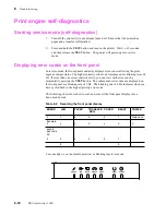
These are the error codes displayed in service mode and their possible causes. These
codes can also be displayed in normal mode, after an error occurs, when you press the
TEST button.
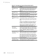
Table 6-3. Print engine error codes and their meanings
Code
Meaning
o o o o o
o
Z
Hex Code 00 No error
Print engine is functioning normally.
o o o o o
Z
Z
Hex Code 01 Drum
position error.
Check the drum-home position sensor; ensure that it is
plugged in. Rotate the drum to see if it interrupts the sensor.
Does the drum rotate during printer operation? Check the
drum motor and belt.
o o o o
Z
o
Z
Hex Code 02 Thermal
Head temperature error.
Ensure that the thermal head is warmed up to operational
level. The thermal head unit should feel warm to the touch;
don't touch the printing elements. If the thermal head is cold,
check power connections and the power supply.
If the power connection and power supply feels too hot,
ensure that the thermal head fan is operating correctly. It
should run during printing and while the thermal head
temperature is above 35
o
C (95
o
F). Also check that the
engine fan blows outward (into the card cage) and the
thermal head fan blows upward.
Ensure that the cable to the transfer roll mark sensors and
thermistor, which senses ambient temperature, is functional.
Ensure that thermal head resistance value, set by DIP
Switch 2, is correct. Refer to the Chapter 9 topic “Adjusting
for best printing quality.”
Are the thermal head cable connectors functional?
If everything else checks out, replace the thermal head.
Refer to the Chapter 8 topic “Thermal head” on page 8-17.
If the thermal head and power supply check out, replace the
print engine control board. Refer to the Chapter 8 topic
“Engine control board” on page 8-39.
o o o o
Z Z
Z
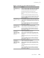
Hex Code 03 EEROM
failure.
Power-down the printer, wait 30 seconds, and power-up. If
the EEROM fails again, replace it (IC 79 is socketed). The
EEROM contains the sensor calibration settings. If you
replaced it, you must run the continuous sensor adjust mode
to restore the calibration settings. Refer to Chapter 5.
o o o
Z
o
o
Z
Hex Code 04 Cover
open error.
If an error occurs while the top or front cover are closed, then
determine if the top cover or front cover interlock switches are
defective. Refer to the topic “Switch and interrupt sensor
checks” on page 9-8 in Chapter 9, “Checks and Adjustments.”
The two switches are wired in series.
Summary of Contents for DECcolorwriter 1000
Page 11: ...Service Manual xi...
Page 16: ...Service Manual xv...
Page 56: ...2 24 DECcolorwriter 1000 2 Installing the Printer and Drivers...
Page 64: ...3 8 DECcolorwriter 1000 3 Verifying the Printer and Host Connections...
Page 70: ...4 6 DECcolorwriter 1000 4 Key Operator Training...
Page 170: ...8 46 DECcolorwriter 1000 8 FRU Disassembly Assembly...
Page 190: ...9 20 DECcolorwriter 1000 9 Checks and Adjustments...
Page 195: ...Service Manual A 5 Field Replaceable Units List A...
Page 198: ...A 8 DECcolorwriter 1000 A Field Replaceable Units List...
Page 204: ...C 6 DECcolorwriter 1000 C Wiring Diagrams...
Page 208: ...D 4 DECcolorwriter 1000 D Test Pattern Generator...


