Service Manual
6-29
Troubleshooting
6
DECcolorwriter 1000 image processors
Image processor normal operation indicators
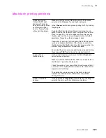
There are three indications that the print engine and its image processor are powered-up
and operating normally: the front panel POWER and READY indicators are on (steady)
and the rear panel STATUS light is blinking.
When the printer is receiving or processing data, the front panel READY light blinks.
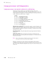
Image processor hard and soft error indicators
Hard errors are image processor self-test failures that would prevent the printer from
printing a page. Hard errors cause the rear panel STATUS light to stop blinking and
remain on or off. Hard errors are also any error that occurs during service mode.
Soft errors are errors that occur during the normal power-up self-test that, while limiting
the printer, would not stop the printer from printing its startpage. A message regarding
the soft error would then be printed on the startup page (even if the startup up page had
been turned off). Soft errors include failures of the expansion SIMMs, as well as the
serial, LocalTalk and parallel ports and their cabling or connections.
Verifying the image processor's operation
The front panel READY light indicates the activity of the image processor. If the light is
on (steady), then the image processor is idle. If READY blinks, then the image
processor is receiving and processing data.
You can verify that the image processor can correctly receive, process and output a print
file by using the Test Pattern Generator. Appendix D “Test Pattern Generator” explains
how to use the Test Pattern Generator.
Summary of Contents for DECcolorwriter 1000
Page 11: ...Service Manual xi...
Page 16: ...Service Manual xv...
Page 56: ...2 24 DECcolorwriter 1000 2 Installing the Printer and Drivers...
Page 64: ...3 8 DECcolorwriter 1000 3 Verifying the Printer and Host Connections...
Page 70: ...4 6 DECcolorwriter 1000 4 Key Operator Training...
Page 170: ...8 46 DECcolorwriter 1000 8 FRU Disassembly Assembly...
Page 190: ...9 20 DECcolorwriter 1000 9 Checks and Adjustments...
Page 195: ...Service Manual A 5 Field Replaceable Units List A...
Page 198: ...A 8 DECcolorwriter 1000 A Field Replaceable Units List...
Page 204: ...C 6 DECcolorwriter 1000 C Wiring Diagrams...
Page 208: ...D 4 DECcolorwriter 1000 D Test Pattern Generator...


