Service Manual
xi
Figures
Figure 1-1.
The DECcolorwriter 1000 (shown with the Lower Tray Assembly)
1-1
Figure 1-2.
Internal features of the DECcolorwriter 1000 print engine
1-3
Figure 1-3.
Sensors and switches on the DECcolorwriter 1000 print engine
1-4
Figure 1-4.
Features of the DECcolorwriter 1000 image processor board
1-7
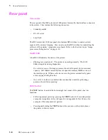
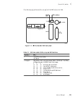
Figure 1-5.
DECcolorwriter 1000 rear panel
1-9
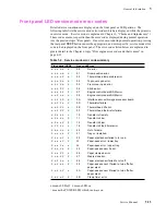
Figure 1-6.
DECcolorwriter 1000 front panel
1-10
Figure 2-1.
The DECcolorwriter 1000 packaging
2-6
Figure 5-1.
The thermal-wax transfer print process
5-3
Figure 5-2.
Print engine board block diagram
5-6
Figure 5-3.
The paper pick process
5-10
Figure 5-4.
Paper clamp opening to receive a sheet of paper
5-11
Figure 5-5.
Clamping the paper
5-11
Figure 5-6.
Positioning the paper for printing
5-12
Figure 5-7.
Printing on the paper
5-12
Figure 5-8.
Raising the thermal head between passes
5-13
Figure 5-9.
Ejecting the print
5-14
Figure 5-10.
Power supply block diagram
5-16
Figure 5-11.
The image processor graphics pipeline
5-18
Figure 6-1.
Measuring the DC voltages (test points)
6-4
Figure 6-2.
Locating the fuses
6-5
Figure 6-3.
24 VDC safety interlocks (top and front covers)
6-7
Figure 6-4.
Proper front idler roller-to-drum alignment (to prevent wrinkling)
6-17
Figure 7-1.
Lubricating the clutches
7-3
Figure 8-1
Removing the Lower Tray Assembly
8-2
Figure 8-2
Removing the cabinet panels
8-4
Figure 8-3
Removing the paper-feed module
8-5
Figure 8-4
Removing the paper-feed circuit board
8-6
Figure 8-5
Removing the paper-feed unit screws
8-7
Figure 8-6
Separating the paper-feedþunit
8-8
Figure 8-7
Removing the pick roller andþclutch
8-9
Figure 8-8
Removing the paper-empty flag
8-10
Figure 8-9
Removing the lower aligningþroller
8-11
Figure 8-10
Removing the paper-pass sensor 1 flag
8-12
Figure 8-11
Removing the upper aligning roller
8-13
Figure 8-12
Removing the feed roller
8-14
Figure 8-13
Removing the exit rollers
8-15
Summary of Contents for DECcolorwriter 1000
Page 11: ...Service Manual xi...
Page 16: ...Service Manual xv...
Page 56: ...2 24 DECcolorwriter 1000 2 Installing the Printer and Drivers...
Page 64: ...3 8 DECcolorwriter 1000 3 Verifying the Printer and Host Connections...
Page 70: ...4 6 DECcolorwriter 1000 4 Key Operator Training...
Page 170: ...8 46 DECcolorwriter 1000 8 FRU Disassembly Assembly...
Page 190: ...9 20 DECcolorwriter 1000 9 Checks and Adjustments...
Page 195: ...Service Manual A 5 Field Replaceable Units List A...
Page 198: ...A 8 DECcolorwriter 1000 A Field Replaceable Units List...
Page 204: ...C 6 DECcolorwriter 1000 C Wiring Diagrams...
Page 208: ...D 4 DECcolorwriter 1000 D Test Pattern Generator...

