background image

8-2

DECcolorwriter 1000

8

FRU Disassembly/Assembly

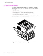
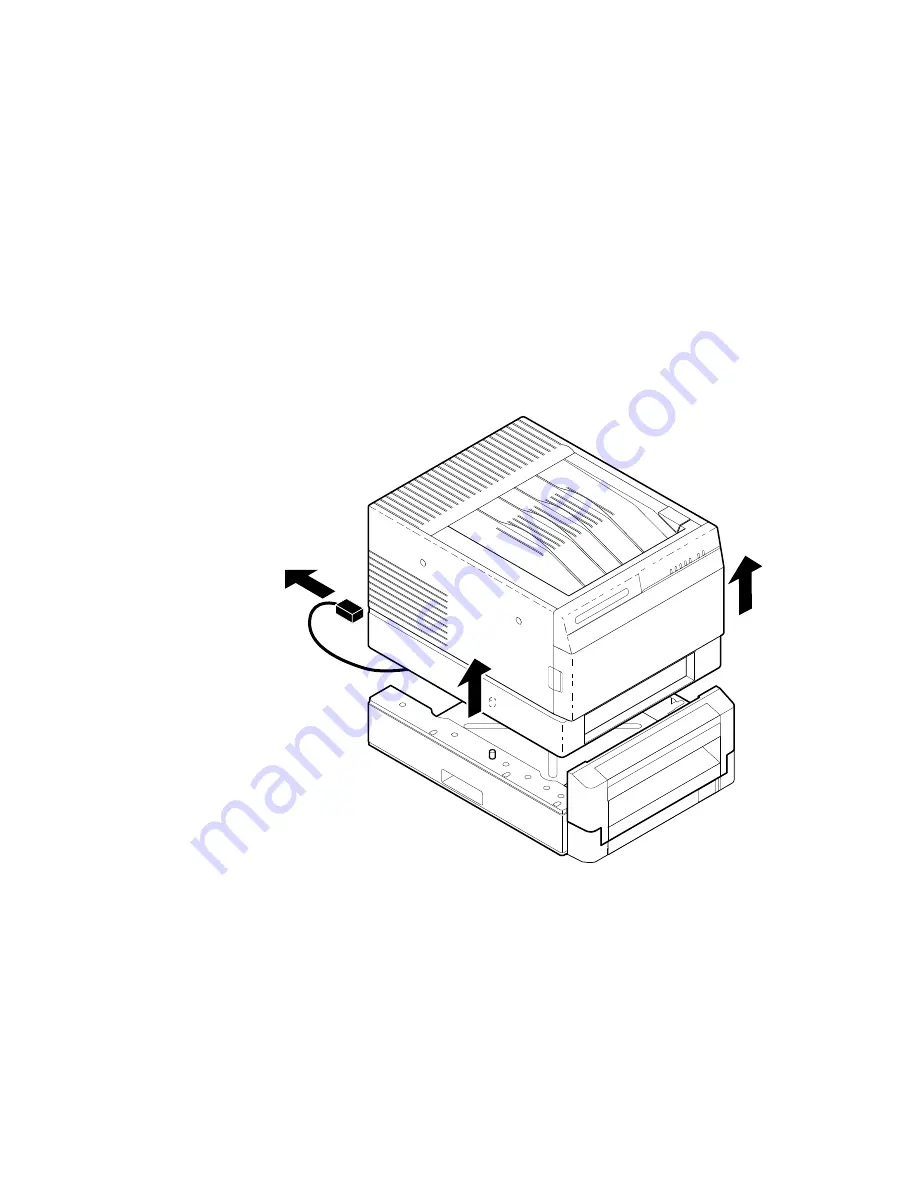
Lower tray assembly

The Lower Tray Assembly, sometimes referred to as the second feeder, is serviced and 
replaced as a unit.  Its construction and operation is very similar to the paper feed unit in 
the print engine.

1.

Turn off the printer.

2.

Unplug the Lower Tray Assembly cable from the rear of the printer.

3.

Lift the printer off of the Lower Tray Assembly.

Reverse these steps to reinstall the Lower Tray Assembly making sure that the printer is 
fully seated over the Lower Tray Assembly's guide pins.

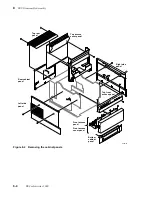
Figure 8-1   Removing the Lower Tray Assembly

8699-56

3

3

2

Summary of Contents for DECcolorwriter 1000

Page 1: ...or use by qualified service personnel only To avoid personal injury do not perform any servicing other than that contained in operating instructions unless you are qualified to do so First printing Fe...

Page 2: ...registered trademarks of the companies with which they are associated PANTONE Colors generated by the DECcolorwriter 1000 are three color process simulations and may not match PANTONE identified soli...

Page 3: ...For example a panel may cover the hazardous area Also applies to a hazard to property including the product itself DANGER A personal injury hazard exists in the area where you see the sign Care of pro...

Page 4: ...ch exposed connections and components while power is on Disconnect power before removing the power supply shield soldering or replacing components Do not wear jewelry Remove jewelry prior to servicing...

Page 5: ...inter 2 8 Connecting the printer to a Macintosh 2 8 LocalTalk connection to a Macintosh 2 8 Connecting the printer to a PC 2 8 Direct connection to a PC 2 8 Connecting the printer to a workstation 2 9...

Page 6: ...tility 3 6 Verifying printing to a workstation using the Error Handler utility 3 7 4 Key Operator Training Printer controls and indicators 4 2 Loading media 4 3 Cleaning 4 3 Clearing paper jams 4 4 Wa...

Page 7: ...e power supply fuses 6 5 Testing for a shorted motor 6 6 24 VDC safety interlocks 6 6 Testing motor resistances 6 8 Media jams and the paper path 6 8 Media based problems 6 8 Paper pick errors 6 9 Pap...

Page 8: ...ECcolorwriter 1000 image processors 6 29 Image processor normal operation indicators 6 29 Image processor hard and soft error indicators 6 29 Verifying the image processor s operation 6 29 Image proce...

Page 9: ...ssembly 8 16 Thermal head 8 17 Drum 8 19 Motors 8 23 Paper feed motor 8 23 Drum motor 8 24 Transfer roll take up motor 8 25 Thermal head lift motor 8 27 Sensors and switches 8 29 Paper pass sensor 1 a...

Page 10: ...or checks 9 8 Calibrating the transfer roll mark sensors reflective sensors 9 10 Calibrating the paper clamp sensor reflective sensor 9 10 Drum belt tension adjustment 9 11 Top margin adjustment 9 12...

Page 11: ...Service Manual xi...

Page 12: ...sses 5 13 Figure 5 9 Ejecting the print 5 14 Figure 5 10 Power supply block diagram 5 16 Figure 5 11 The image processor graphics pipeline 5 18 Figure 6 1 Measuring the DC voltages test points 6 4 Fig...

Page 13: ...gure 8 30 Removing the paper clamp sensor 8 34 Figure 8 31 Disconnecting the wiring harnesses and removing the card cage 8 35 Figure 8 32 Removing the card cage and power supply 8 36 Figure 8 33 Remov...

Page 14: ...vice Manual xiii Figure C 1 Print engine control board connector diagram C 4 Figure C 2 Print engine wiring diagram C 5 Figure D 1 Plugging the Test Pattern Generator into the printer s parallel port...

Page 15: ...fying the DEVPARAMS PS file 2 21 Table 6 1 Motor and solenoid resistances 6 8 Table 6 2 Decoding the front panel display 6 18 Table 6 3 Print engine error codes and their meanings 6 19 Table 9 1 Selec...

Page 16: ...Service Manual xv...

Page 17: ...and provides information on installing and verifying the printer and training printer users The latter half of the manual includes troubleshooting guides adjustment procedures assembly disassembly pro...

Page 18: ...module In addition the DECcolorwriter 1000 supports a high resolution 300 x 600 dots per inch printing mode For host image input the controller also features a standard parallel port an RS 232 serial...

Page 19: ...ard Drum Exit roller belt Lower exit roller Paper feed module Feed roller Pick roller Print feed circuit board Power supply Paper feed motor Transfer roll take up motor Interconnect board Drum motor D...

Page 20: ...oll low sensor Thermal head position sensors 2 mounted on top cover Transfer roll core sensor right DIP Switch 2 DIP Switch 1 Paper clamp sensor Transfer roll mark sensor Top cover open sensor Drum ho...

Page 21: ...of the two transfer roll core sensors tell the print engine what type of transfer roll is installed The length of the cores long or short actuate the switches Long cores close the switches turning th...

Page 22: ...elect either paper or transparency film n Letter Plain Paper This tray is sized for 8 5 x 11 inch plain paper It is used when printing with the Plain Paper Transfer Roll n A4 Perforated Media This tra...

Page 23: ...nual 1 7 General Information 1 Image processor boards Figure 1 4 Features of the DECcolorwriter 1000 image processor board 8699 05 ROM Font SIMM RAM SIMM J14 J6 J1 J2 I O connector Interconnect board...

Page 24: ...printer is operating normally The LED blinks irregularly during diagnostics If a soft error occurs the image processor board will operate but in a reduced capacity Soft failures include failure of exp...

Page 25: ...p Reset 2 through 4 Diagnostics modes serial parameters fixed at 1200 baud Vivid Blue Configuration page NVRAM Reset Demo pages 2 3 4 Normal power up self tests Fixed RS 232 parameters Used NVRAM stor...

Page 26: ...BON On indicates the transfer roll is low and will soon need to be replaced Blinking indicates the transfer roll is empty MEDIA On indicates the paper tray is empty Blinking together with the JAM ligh...

Page 27: ...tion error o o o o Z o Z 02 Thermal head temperature error o o o Z o o Z 04 Top cover open error o o o Z o Z Z 05 Front cover open error o o o Z Z o Z 06 Strobe error o o o Z Z Z Z 07 Engine control b...

Page 28: ...mately 18 kgs 40 lbs Print engine weight only add 26 4 kgs 12 lbs for Lower Tray Assembly Shipping weight is not to exceed 32 kgs 70 lbs Table 1 6 Printer clearances Clearances Value Top 45 7 cm 18 in...

Page 29: ...nta and cyan 214 prints per roll Black Transfer Roll features all black panels 880 prints per roll The printer automatically senses the transfer roll type by the size of the transfer roll cores Addres...

Page 30: ...image processor electronics which draw power from the print engine Current rating 115 VAC configuration 7 amp max 1 amp min 220 VAC configuration 7 amp max 1 amp min Primary voltage fusing 115 VAC co...

Page 31: ...de Operating Non operating 0 to 4570 m 15 000 ft at 25 C 0 to 15200 m 50 000 ft Vibration shock Non Operating vibration Non operating shock Operating shock 0 75g 25 minutes in three mutually perpendic...

Page 32: ...Information Processing Business Equipment n EC EN60950 Safety of Information Technology Equipment including Electrical Business Equipment n EC EN55022 Limits and methods of measurement of radio inter...

Page 33: ...nistration will be available for the scheduled installation and that all necessary cables will be available n Unpacking This is the procedure for taking the printer out of its shipping box n Testing T...

Page 34: ...o parallel o LocalTalk n In the event that the printer is to be installed into a network environment will a network administrator be available to help in assigning network names and addresses for the...

Page 35: ...r LocalTalk connector Customers can obtain an adapter from their dealer The printer requires the following environmental conditions n Temperature 15 to 35 o C 59 to 95 o F n Humidity 20 to 80 relative...

Page 36: ...adra n Operating System 6 0 7 or later n 4 Mbytes RAM PC n IBM AT PS 2 or compatible with a 386 or later CPU a 5 25 or 3 5 inch floppy drive and a hard disk drive 2 Mbytes RAM DOS system DOS 3 1 or la...

Page 37: ...rinter n Printer n Paper tray n Power cord n Getting Started folder n Cleaning kit n Supplies information sheet n Transfer roll n Paper n Transparencies n User manual n Printer drivers and utilities r...

Page 38: ...ure that the paper clamp is positioned under the bail rollers This prevents the bail rollers from denting the soft material of the drum In normal operation the paper clamp is automatically parked in t...

Page 39: ...Caution When moving a printer featuring the Lower Tray Assembly be sure to grasp the Lower Tray Assembly by its hand holds on both sides to lift it and the printer together Carry the printer by carryi...

Page 40: ...for a Macintosh will most likely be either a LocalTalk network or an Ethernet network LocalTalk connection to a Macintosh 1 Turn off the printer LocalTalk protocol requires that you attach the LocalTa...

Page 41: ...a workstation 1 Turn off the printer Turn off the host computer 2 Attach the parallel interface cable to the workstation Attach the other end to the printer Alternatively attach the serial cable to th...

Page 42: ...ns and print quality mode n Pages Printed n RAM installed n Image processor version firmware n Adobe PostScript version software n Type of transfer roll loaded If the printer detects a non fatal error...

Page 43: ...ttings Table 2 1 Configuration page settings for DECcolorwriter 1000 printers Parameter Description Saved in NVRA M Default Limits or alternate choices Printer type The name of the product yes DECcolo...

Page 44: ...e of interpreters in use at the port yes PostScript Level 2 Not installed Disabled interpreter Parallel port Encoding Indicates the type of data encoding the parallel port is inspecting yes ASCII Bina...

Page 45: ...rinting Reference for more details To install the DECcolorwriter 1000 driver with system 6 0 7 or higher 1 Place the DECcolorwriter 1000 Drivers and Utilities diskette Macintosh into the disk drive 2...

Page 46: ...ears 4 Choose the Add button 5 In the List of Printers select Install Unlisted or Updated Printer 6 Choose the Install button 7 Type in the drive the PC diskette is in for example drive B and choose t...

Page 47: ...Printers Network Connections dialog box Fill in each item according to your configuration then choose the OK button Refer to your Windows documentation for details or ask your network administrator fo...

Page 48: ...e of bitmapped raster images by improving the image transfer time from the computer to the printer and by improving the image processing time in the printer This option is only available to applicatio...

Page 49: ...riate floppy drive and the directory WPD Choose your printer and then click the OK button When asked to insert a diskette with the updated PSCRIPT DRV file enter system as the location so that the cur...

Page 50: ...proper printer driver name If it is listed select it otherwise point the cursor to any other driver listed and click the right mouse button Click Install from the menu options 7 In the Install New Pr...

Page 51: ...kely causes of printer errors is that the document and device defaults do not match c Select Options and make sure that it is set to DECcolorwriter 1000 If not repeat the previous steps While in this...

Page 52: ...printer s serial port The following example sets flow control to Xon Xoff parity to none data bits to 8 stop bits to 2 and the baud rate to 9600 In the example below the changes are persistent across...

Page 53: ...in the following table The values are case sensitive they must be entered exactly as shown 2 Use the DOS COPY command to send the DEVPARAM PS file to the printer for example COPY DEVPARAM PS COM1 Sub...

Page 54: ...intcap file 2 Add to the printcap file a new print queue name and set the port parameters as needed Add the following to the printcap file px br 9600 rw fc 00000374 fs 00000003 xc 0 xs 0040060 mx 0 sf...

Page 55: ...nual 2 23 Installing the Printer and Drivers 2 px br 9600 rw fc 00000374 fs 00000003 xc 0 xs 0040040 mx 0 sf sh sd var spool px if var spool px if lp dev ttya 5 To print a PostScript file type lpr Ppx...

Page 56: ...2 24 DECcolorwriter 1000 2 Installing the Printer and Drivers...

Page 57: ...ng the printer drivers installed on the Macintosh Select the driver icon DECcolorwriter 1000 by clicking on it once If the host and the printer are a part of a zone you should first select the printer...

Page 58: ...driver can send a file to the printer If the printer does not make a print then there may be a problem with the printer driver In this case if possible you should verify that the Macintosh can print...

Page 59: ...ies files 4 Double click on its self sending arrow icon to open and send the file to the printer Be sure that the DECcolorwriter 1000 is selected This loads the error handling utility into the printer...

Page 60: ...r by double clicking the Program Manager icon 3 Open the Accessories window by double clicking the Accessories icon 4 Double click on the Write icon If Write is not available you can use any other tex...

Page 61: ...re available a You may print the contents of a window by pointing to that window and pressing Print Screen b You may print the full screen by first opening any window placing the cursor on the desktop...

Page 62: ...r Utility diskette 2 Copy the file ADVEHAND PS to the PC s hard disk or use the file from the diskette 3 Use the DOS COPY command to send the file to the printer For example COPY advehand ps LPT1 If n...

Page 63: ...e in the PrinterUtility diskette 2 Copy the file ADVEHAND PS to the workstation s hard disk or use the file from the diskette 3 Make sure that the printer port is configured to receive PostScript then...

Page 64: ...3 8 DECcolorwriter 1000 3 Verifying the Printer and Host Connections...

Page 65: ...s section covers the last portion of the printer installation training the printer s key operator The steps you follow here place an emphasis on encouraging the key operator to read and use the printe...

Page 66: ...selected at the host computer through the printer driver n Show where the functions of the rear panel switches are explained in the user manual TEST button Explain the function of this switch n Show...

Page 67: ...e endcaps only Fingerprints can affect print quality n Demonstrate how to remove the transfer roll n Show where handling the transfer roll is explained in the user manual n Emphasize that cleaning the...

Page 68: ...they could block the paper tray from being inserted into the printer Show how the pick rollers can be manually rotated into their proper position n Demonstrate how to push the media down in the paper...

Page 69: ...ter as well as printer accessories such as software and printer stands that customers may be interested in Additionally some supplies are listed in the user manual United States Customers can call 1 8...

Page 70: ...4 6 DECcolorwriter 1000 4 Key Operator Training...

Page 71: ...a high level description of the thermal wax transfer printing technology and how the printer employs it Following that is a high level discussion of the image processor board and how it receives data...

Page 72: ...ed paper or transparency film is drawn past a thin Mylar ribbon called a transfer roll which is coated with sequential bands of colored wax yellow magenta and cyan A heating device called a thermal he...

Page 73: ...a complete color image After the three passes the finished copy is ejected from the printer The wax transfer roll is supplied on one spool feeds past the thermal head and drum for printing and collect...

Page 74: ...of the paper where colored wax is to be applied Because of the extra pass required for printing on plain paper and the fact that the drum moves in a slower half step mode while laying down the precoa...

Page 75: ...mixed together to simulate other colors called secondary colors When tiny dots of two primary colors are intermixed your eye perceives a third color That is how the print engine can use just three bas...

Page 76: ...ck diagram consists of nine major functions n Central processing unit CPU n Interface n Data controller and data buffer n Timing controller n Dot compensator n Head controller n Thermal head n Mechani...

Page 77: ...the heat controller Heat controller dot compensation Each thermal heating element must receive sufficient energy to melt wax properly Too much energy and the wax dot smears when printed Too little en...

Page 78: ...electrical design the print engine actually uses a drive signal multiplexing scheme to energize the heating elements During printing the head controller activates a pair of heating element segments fr...

Page 79: ...eet of paper to the aligning rollers As the paper passes through the paper feed unit it triggers paper pass sensor 1 which checks to see if the paper made it to the aligning rollers Note that the acti...

Page 80: ...he spring loaded paper clamp waiting in the clamp open position to capture the leading edge of the paper Figure 5 3 The paper pick process Figure 5 4 Paper clamp opening to receive a sheet of paper 86...

Page 81: ...ermal head ready for printing The position of the drum is determined by the drum motor At this time the transfer roll motor is energized to draw the transfer roll to its start position with the leadin...

Page 82: ...r The sheet of paper is drawn past the thermal head three times to form a complete image When the first pass yellow printing is completed the thermal head lift motor raises the thermal head to its sta...

Page 83: ...rinting This is one of the reasons for the DECcolorwriter 1000 s faster print times With plain paper printing using the 4 pass Plain Paper Transfer Roll the first pass lays down a precoat layer on the...

Page 84: ...ckward for a set amount of time drives the lower and upper exit rollers which pull the print through the rollers and out to the printer s output tray The print engine checks to make sure that the pape...

Page 85: ...ted from a flyback converter system 12 VDC is supplied to the image processor board for specialized circuitry n 25 5 VDC generated from a pulse width modulated PWM system 25 5 VDC is used for the 24 V...

Page 86: ...rheating is detected by a thermostat that also shuts down the pulse width modulator oscillator Figure 5 10 Power supply block diagram L SW1 F1 F2 N FG Input filter Rush current preventing circuit Rect...

Page 87: ...ed AppleTalk protocol n The PostScript data received through the I O serializer is routed to the PostScript interpreter The PostScript interpreter generates display lists which describe objects and te...

Page 88: ...he color plane data to the print engine The control loop also monitors the control and error signals fed back from the print engine Figure 5 11 The image processor graphics pipeline 8699 18 Image proc...

Page 89: ...e printer initialization 2 The thermal head lift motor energizes to raise the thermal head into its standby position if it is out of position The position is sensed by the thermal head position sensor...

Page 90: ...4 Select any test pattern using the Test Pattern Generator s four DIP switches and then press its print button 5 After the print is made remove the Test Pattern Generator If the printer prints a test...

Page 91: ...from its power outlet 2 AC Input With the VOM set to measure AC voltages measure for power being supplied to the printer It should measure between 87 to 128 VAC 115 VAC nominal or 174 to 250 VAC 220 V...

Page 92: ...ng the power supply fuses If the 5 VDC and 24 VDC voltages measure correctly but the printer does not operate correctly then proceed to the procedure 24 VDC safety interlocks Figure 6 1 Measuring the...

Page 93: ...cage and power supply on page 8 35 for the procedure to follow to access the fuses 2 Visually and with a VOM check to determine that the fuses are good If the fuses are good but the printer s power s...

Page 94: ...e 8 35 24 VDC safety interlocks The printer features two 24 VDC safety interlocks They are two switches in series that can disconnect 24 VDC to all the motors The 24 VDC actually 25 5 VDC supplied to...

Page 95: ...If motor resistances are correct replace the engine control board Refer to the Chapter 8 topic Engine control board on page 8 39 Figure 6 3 24 VDC safety interlocks top and front covers 8345 21 Top c...

Page 96: ...hen using coated paper with the 3 Color Transfer Roll be sure that the coated side of the paper faces up in the tray Fanning perforated media eliminates its tendency to double pick due to the perforat...

Page 97: ...t is not go to the topic Checking the paper feed motor and drive train on page 6 11 Otherwise go to Step 5 In their starting position the pick rollers flat side should face downward 5 Clean the pick r...

Page 98: ...drum home position sensor Refer to the Chapter 9 topic Switch and interrupt sensor checks on page 9 8 4 Clean the paper clamp with alcohol and a lint free cloth to ensure that it is fully gripping th...

Page 99: ...5 VDC is being supplied to the motor If it is go to Step 3 If it is not inspect the paper feed motor s wiring harness If the harness is good then troubleshoot the power supply Refer back to the topic...

Page 100: ...er roll jam 1 Ensure that the transfer roll is not installed backwards It should feed off the bottom of the supply roll and over the top of the take up roll The black stripe should be oriented under t...

Page 101: ...rly tensioned Refer to the Chapter 9 topic Drum belt tension adjustment on page 9 11 3 Check the drum motor by measuring the resistance of its windings Refer to Table 6 1 for the expected winding resi...

Page 102: ...a drum shim washer The shim washers are included in the hardware parts kit Refer to the Chapter 8 topic Drum on page 8 19 4 Check the drum drive belt for proper tension Refer to the Chapter 9 topic Dr...

Page 103: ...2 Ensure that the thermal head power and data cables are properly connected 3 Measure the power being supplied to the thermal head refer to the earlier topic Verifying power supply operation on page 6...

Page 104: ...ells the engine control board of the print engine s ambient temperature An erroneous thermistor value could cause the print engine to use an incorrect thermal head voltage value for printing 6 Ensure...

Page 105: ...e drum The sleeves should be firmly attached to the roller they should not slide or rotate on the roller Note that the right sleeve is located 2 mm 0 08 in inside the right notched edge of the drum Re...

Page 106: ...highest priority error code is displayed at a blinking rate of 4 Hz If more than one error condition exists you can view each error code by momentarily pressing the TEST button The subsequent error c...

Page 107: ...above 35o C 95o F Also check that the engine fan blows outward into the card cage and the thermal head fan blows upward Ensure that the cable to the transfer roll mark sensors and thermistor which sen...

Page 108: ...or board If the error recurs run diagnostics on the image processor board as explained in the topic Image processor self diagnostics on page 6 30 at the end of this chapter o o Z Z o Z Z Hex Code 0D T...

Page 109: ...not check the sensor and its wiring harness Refer to the topic Switch and interrupt sensor checks on page 9 8 in Chapter 9 Checks and Adjustments Check the transfer roll mark sensors and transfer roll...

Page 110: ...t reach the paper pass sensor 1 check to see if media was picked from the tray Clean the paper pick rollers in the print engine Refer to Chapter 7 topic Cleaning Ensure that the alignment roller pres...

Page 111: ...ers for proper operation Check for blockage at the paper exit sensor or paper tray Ensure that the paper exit sensor operates correctly and is properly adjusted Refer to the topic Switch and interrupt...

Page 112: ...ety interlocks on page 6 6 Media tray indicates empty when it is not If there is media in the tray then check the media tray microswitches on the right side of the tray slot Check to see if the paper...

Page 113: ...ript printer such as an Apple LaserWriter If the file does not print on the black and white PostScript printer this may mean that the problem may be application or network related Ensure that the prin...

Page 114: ...ry indefinitely Ensure that the print engine can print by pressing and holding the rear panel TEST switch to print an internal test print Is the printer in PostScript mode Check this by sending the fi...

Page 115: ...elect Printer Setup Options Printer Features Media Selection You are now at theOptions window Select Adjust Vivid Blue This Options window can also be accessed through the Control Panel Printers optio...

Page 116: ...arallel printing Ensure that the print file ends with a CTRL D character CTRL D indicates the end of file which the printer responds to by closing host to printer communications and then processing an...

Page 117: ...ing service mode Soft errors are errors that occur during the normal power up self test that while limiting the printer would not stop the printer from printing its startpage A message regarding the s...

Page 118: ...interaction If a problem is encountered with the image processor s expansion memory or other options then the information is printed on the printer s start up page Normal power up tests take between 4...

Page 119: ...no errors were detected and that the image processor s CPU is running Printing the configuration page While the printer is idle if you toggle Switch 4 up and then down as detailed on the previous pag...

Page 120: ...Flip DIP Switch 1 up and back down to reinitialize the printer 3 Observe the rear panel LED it quickly flashes four times for 1 second and then is off for 1 second This pattern repeats for 10 seconds...

Page 121: ...with an alcohol dampened cloth 3 Clean the pick rollers Customers can either do this with an alcohol dampened lint free cloth or use the pick roller cleaning tray provided in the cleaning kit Each tim...

Page 122: ...printer s bearings and motors are lifetime factory lubricated However over time and under certain extreme operating conditions oil and grease may dry out causing squeaks and rumbling noises in the pri...

Page 123: ...for noise reduction purposes Apply it sparingly so that the grease does not fling off of the gears when they turn You need only to apply a dab of grease to a single gear and the grease will migrate th...

Page 124: ...ook for these problems n Loose rubber particles below the belts indicate a worn belt n Missing teeth in the belts n Cracking or moderate fraying a small amount of fraying is inevitable so look for oth...

Page 125: ...n Extension tip n 1 POSIDRIV tip n 2 POSIDRIV tip n Tweezers n Hex wrench kit n G 311S lubricating grease n Antistatic mat n Flat blade screwdriver n Needle nose pliers n Volt ohm meter such as a Tekt...

Page 126: ...is very similar to the paper feed unit in the print engine 1 Turn off the printer 2 Unplug the Lower Tray Assembly cable from the rear of the printer 3 Lift the printer off of the Lower Tray Assembly...

Page 127: ...rear panel slightly before removing a side panel Before you remove the following panels you must first remove the panels noted above n Rear cabinet panel remove the top rear panel first n Top front ca...

Page 128: ...bly Assembly Figure 8 2 Removing the cabinet panels 8699 57 Top rear panel Top access cover panel Rear cabinet panel Left side panel Right side panel Top front access panel Front access panel Bottom c...

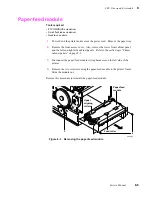
Page 129: ...pic Printer cabinet panels on page 8 3 3 Disconnect the paper feed module wiring harnesses on the left side of the printer 4 Remove the two screws securing the paper feed module to the printer frame S...

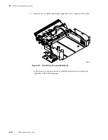
Page 130: ...procedure Paper feed module on page 8 5 3 Remove the two screws securing the paper feed circuit board to the paper feed module One screw is reached through an access hole Slide the board out of the w...

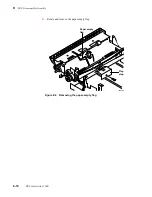
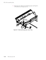
Page 131: ...of the paper feed module For reassembly note the alignment pins in the top half and the receiving holes in the bottom half Ensure that they properly line up during reassembly Figure 8 5 Removing the p...

Page 132: ...sembly 5 Separate the two halves and flip the upper half over to expose all the rollers At this point you can proceed to any individual roller removal procedures explained on the following pages Figur...

Page 133: ...ptional step 1 Remove the E ring securing the pick roller clutch Remove the clutch For reassembly note the keyed shaft the clutch fits onto 2 Remove the two E rings securing the pick roller to the upp...

Page 134: ...8 10 DECcolorwriter 1000 8 FRU Disassembly Assembly 4 Rotate and remove the paper empty flag Figure 8 8 Removing the paper empty flag 8699 70 Paper empty flag Flag stop...

Page 135: ...nal step 1 Remove the E ring securing the aligning roller clutch Remove the clutch For reassembly note the keyed shaft the clutch fits onto 2 Remove the two E rings securing the lower aligning roller...

Page 136: ...FRU Disassembly Assembly 3 Paper pass sensor 1 flag removal Rotate the paper pass sensor flag about 180o and slide it out of the paper feed unit Figure 8 10 Removing the paper pass sensor 1 flag 8699...

Page 137: ...ning roller white nylon refer to Figure 8 6 2 Remove the two tensioning springs holding down each end of the upper aligning roller 3 Remove the two E rings securing the upper aligning roller Remove th...

Page 138: ...Figure 8 6 2 Remove the two E rings securing the feed roller 3 Remove the white nylon gear and its pin 4 Remove the feed roller If necessary remove the right end bushing to create more clearance for r...

Page 139: ...Lower exit roller Remove the E rings securing the lower exit roller pulley 4 Remove the lower exit roller pulley roller bushings and the paper eject belt 5 Upper exit roller Remove the E rings securin...

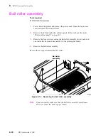
Page 140: ...panels on page 8 3 3 Remove the four screws securing the bail roller assembly two at each end one inside the frame and one outside to the print engine frame 4 Remove the bail roller assembly Reverse t...

Page 141: ...de pin is screwed into the printhead block Note If you replace a thermal head with a Kyocera brand thermal head cut out the two white 0 resistors located at the center of the engine control board Repl...

Page 142: ...rap so that it does not interfere with the thermal head lift belt Warning Do not disconnect the ground strap from the back of the thermal head only disconnect it from the head lift motor bracket Not r...

Page 143: ...4 Remove the drum belt from the drum pulley 5 Use a 2 mm hex wrench to loosen the two set screws securing the drum pulley in place Remove the drum pulley spring and washers Also remove the drum shaft...

Page 144: ...he E rings and bronze bushings from each end of the front idler roller Remove the roller 7 Remove the bail roller assembly by removing the pair of screws at each end of the assembly Figure 8 17 Removi...

Page 145: ...shaft to the print engine frame Also remove the shaft s bronze bushing Note During removal and replacement be careful not to scratch or damage the drum Defects in the surface of the drum can affect p...

Page 146: ...screws are positioned over the flat cutouts in the shaft Tighten the set screw that goes into the countersunk hole first Then tighten the set screw that sets against the other flat cutout Otherwise b...

Page 147: ...arlier topic Printer cabinet panels on page 8 3 3 Disconnect the wiring harness leading to the paper feed motor 4 Remove the two screws securing the paper feed motor to the print engine frame Remove t...

Page 148: ...belt and then tighten the set screw to hold the belt in its loosened position 4 Remove the drum belt from the drum pulley 5 Disconnect the drum motor s wiring harness leading to the print engine contr...

Page 149: ...the transfer roll 3 Remove the left side cabinet panel Refer to the earlier topic Printer cabinet panels on page 8 3 4 On the inside of the printer loosen the transfer roll take up gear s two set scre...

Page 150: ...two screws securing the transfer roll take up motor to the print engine frame Remove the motor Reverse these steps to reinstall the transfer roll take up motor When you install the take up gear be sur...

Page 151: ...transfer roll mark sensors are mounted to this bracket Remove the transfer roll mark sensors shield Note Since you remove the transfer roll mark sensors to gain access to the printhead lift motor upo...

Page 152: ...ead lift motor shaft 5 Remove the screw securing the thermal head lift motor in place Remove the motor with an upward twisting motion 6 Disconnect the thermal head lift motor s wiring harness Reverse...

Page 153: ...fer to the earlier topic Paper feed module on page 8 5 Thermal head position sensors These sensors are mounted on a small circuit board that attaches to the top side of the top cover It is easily acce...

Page 154: ...r down the printer and remove the power cord 2 Remove the paper feed module as explained in the previous procedure Paper feed module on page 8 5 3 Remove the two screws securing the paper feed circuit...

Page 155: ...ring the top half of the paper feed module Separate the two halves and flip over the upper half 5 Paper pass sensor 2 Unclip paper pass sensor 2 and remove it and its wiring harness leading to the pap...

Page 156: ...paper feed module Unhinge the bracket to access the tray sensor circuit board 8 Remove the screw securing the paper tray sensor circuit board to the bracket Remove the circuit board Reverse these step...

Page 157: ...ic Card cage and power supply on page 8 35 4 Disconnect the sensor s 3 wire wiring harness from the engine control board CN7 Clip the tie wrap it shares with the other wiring harnesses 5 Unclip the se...

Page 158: ...cedure Drum on page 8 19 4 Disconnect the paper clamp sensor s wiring harness 5 Remove the two screws securing the paper clamp sensor in place Reverse these steps to reinstall the paper clamp sensor R...

Page 159: ...cabinet panels Refer to the earlier topic Printer cabinet panels on page 8 3 3 Disconnect all wiring harnesses from the card cage 4 Disconnect the four screws securing the card cage to the print engin...

Page 160: ...print engine As you slide the card cage out you can disconnect the thermal head power supply harness from the power supply Fuses Note the location of the power supply s fuses Engine fan Note that the...

Page 161: ...you ll reverse the 115 220 AC settings 4 Disconnect the AC voltage wiring harness from CN2 next to the fuses of the power supply circuit board 5 Disconnect the fan wiring harness from CN5 of the power...

Page 162: ...supply After replacing the power supply run the adjustment Thermal head temperature adjustment on page 9 14 to ensure that the printhead is calibrated to the new power supply Figure 8 33 Removing the...

Page 163: ...page 8 5 Engine control board 1 Power down the printer Leave the power cord plugged in to provide a ground path for static discharges 2 Remove the left side and top rear cabinet panel Refer to the ea...

Page 164: ...ard be sure to exchange the NVRAM IC 5 from the old board into the new board The NVRAM IC contains the printhead temperature and sensor calibration setting If for some reason you must reprogram the NV...

Page 165: ...nd the image processor board from the card cage Refer to the procedures Engine control board on page 8 39 and Image processor board on page 8 43 4 Remove the card cage and power supply assembly as exp...

Page 166: ...ear and rear cabinet panels Refer to the earlier topic Printer cabinet panels on page 8 3 3 Remove the screws securing the I O board to the card cage 4 Disconnect the I O board s ribbon cable from the...

Page 167: ...edure I O board on page 8 42 6 Lift out the image processor board Note If you are replacing an old image processor board for a new board swap the NVRAM IC U672 from the old board into the new board Th...

Page 168: ...dule upright until it locks in place b When properly inserted a tab on each end of the connector slips into a hole on each end of the RAM SIMM Also a pawl on each end of the connector latches around e...

Page 169: ...upright until it locks in place b When properly inserted a tab on each end of the connector slips into a hole on each end of the module Also a pawl on each end of the connector latches around each en...

Page 170: ...8 46 DECcolorwriter 1000 8 FRU Disassembly Assembly...

Page 171: ...int quality Required tools summary n Magnetic tip screwdriver 8 5 ins n Extension tip n 1 POSIDRIV tip n 2 POSIDRIV tip n Tweezer n Hex wrench kit n G 311S lubricating grease n Antistatic mat n Needle...

Page 172: ...o the Chapter 8 topic Printer cabinet panels on page 8 3 3 Set all the DIP 1 Switches off 4 Press and hold the TEST button and turn on the printer Release the TEST button The printer is now in service...

Page 173: ...Pattern 3 Composite black fill C M Y CMY Test Pattern 4 25 fill CMY Test Pattern 5 Dither CMY Test Pattern 6 Wrinkle 1 CM Test Pattern 7 Rag patch half step CMY Test Pattern 8 Wrinkle 2 CMY Test Patte...

Page 174: ...ermal head in print standby position Transfer roll feeds continuously Second feeder connection test Paper path check pick feed clamp and eject Leading edge margin tolerance adjust generally a manufact...

Page 175: ...rns off 8 Set DIP Switch 1 3 off to stop the test Transfer roll feed check Note Don t run this test for a prolonged period of time since it consumes the transfer roll 1 Turn off the printer 2 Remove t...

Page 176: ...ing actions n paper pick n paper clamp n paper eject 8 Set DIP Switch 1 3 off to stop the test Tray select Use this mode to select from which tray if the optional lower tray is installed the printer w...

Page 177: ...on page 8 3 3 Press and hold the TEST button and turn on the printer Release the TEST button The printer is now in service mode 4 Set all the DIP 1 Switches off 5 Set DIP Switches 1 5 1 6 and 1 7 on...

Page 178: ...eder Tray switch 3 second feeder Paper empty sensor second feeder tray Mode 5 Paper pass sensor 1 Paper pass sensor 2 Paper exit sensor Drum home position sensor Mode 6 Transfer roll low sensor 1 Turn...

Page 179: ...roll Transfer roll core sensor 2 actuate the switch at the right end of the supply roll Mode 3 PAPER TRANSFER ROLL COVER READY Tray switch 1 standard feeder top switch Tray switch 2 standard feeder m...

Page 180: ...eflected light they detect from the white reflection plate located beneath the sensors LED READY will blink rapidly 8 Set DIP Switch 1 3 off to exit the mode Calibrating the paper clamp sensor reflect...

Page 181: ...hapter 8 topic Printer cabinet panels on page 8 3 3 Loosen the drum belt tensioner set screw The tensioner spring will automatically adjust the belt to the correct tension 4 Rotate the drum pulley sli...

Page 182: ...ll four sides is 5 mm 3 mm 1 Turn off the printer Ensure that the paper tray is filled 2 Remove the rear cabinet panel to access the engine control board Refer to the Chapter 8 topic Printer cabinet p...

Page 183: ...bottom margin will get correspondingly smaller Conversely negative numbers decrease the distance the paper is inserted into the paper clamp 8 Press the TEST button to store the new value into the prin...

Page 184: ...o the setting that matches the resistance value printed on the thermal head This step sets a nominal value for the thermal head You may change the switch setting to achieve the best print quality 3 Pr...

Page 185: ...ch is on Table 9 5 Setting thermal head temperature based on thermal head resistance Dip Switches 2 1 2 2 2 3 2 4 Resistance printed on thermal head 1315 1316 to 1345 1346 to 1375 1376 to 1405 1406 to...

Page 186: ...the print 7 Examine the print for speckle Speckles appear as pale blue dropouts in the blue field of the print If speckle appears go to Step 10 Otherwise go to Step 8 Caution The pitch adjustment rota...

Page 187: ...Service Manual 9 17 Checks and Adjustments 9 Figure 9 3 Adjusting the thermal head pitch 8 Pitch adjustment nut Thermal head elements Drum Pitch adjustment nut Thermal head 8699 91A...

Page 188: ...to unload the paper clamp Caution Be sure to loosen the lock screws before rotating the eccentric nuts 5 Through an access hole on each side of the printer loosen the lock screw securing the eccentric...

Page 189: ...hecks and Adjustments 9 Figure 9 4 Setting the paper clamp adjustment 8699 90A 7 Paper clamp Access hole High side mark on eccentric nut Set it so the mark always faces toward the front of the printer...

Page 190: ...9 20 DECcolorwriter 1000 9 Checks and Adjustments...

Page 191: ...the DECcolorwriter 1000 Color Printer Changes to the instruments are made to accommodate improved components as they become available It is important when ordering parts to include the following info...

Page 192: ...18 8938 00 1 CABINET LEFT SIDE A 1 2 118 8937 00 1 CABINET BACK LOWER A 1 3 118 8936 00 1 CABINET BACK UPPER A 1 4 118 8932 00 1 CABINET TOP WITH OPEN LEVER A 1 5 118 8939 00 1 CABINET RIGHT SIDE A 1...

Page 193: ...Service Manual A 3 Field Replaceable Units List A Figure A 1 The printer exterior FRUs 8699 76A 1 2 3 4 5 6 7 8 9...

Page 194: ...MP SENSOR A 2 15 29 31567 01 118 8840 00 1 BELT KIT A 2 16 29 31560 01 118 8845 00 1 DRUM ASSY KIT A 2 17 118 8852 00 1 CIRCUIT BOARD SENSOR RIBBON MARK A 2 18 29 31563 01 118 8853 00 1 MOTOR HEAD LIF...

Page 195: ...Service Manual A 5 Field Replaceable Units List A...

Page 196: ...6 DECcolorwriter 1000 A Field Replaceable Units List Figure A 2 Exploded view of the printer 2 3 1 4 7 6 8 9 10 11 12 15 13 14 15 18 17 19 5 16 33 25 24 26 28 15 27 32 31 30 29 23 22 21 20 6 8699 77A...

Page 197: ...4 tray EK LF02E UM 070 8931 00 1 MANUAL TECH USER DECcolorwriter 1000 EK LF02A UM 070 8936 00 Contains one each of the following manuals French Italian German Spanish The EK numbers are for reference...

Page 198: ...A 8 DECcolorwriter 1000 A Field Replaceable Units List...

Page 199: ...ctor CN2 Pin Signal Pin Signal Pin Signal Pin Signal 1 CVOPN1 0 10 PSS 0 19 FA2 0 28 5 VDC 2 PEJCT 0 11 5 VDC 20 FAN2 0 29 GND 3 CVOPN2 0 12 GND 21 FB2 0 30 RTYP2 4 DRMT 0 13 PS1 0 22 FBN2 0 31 no con...

Page 200: ...HLFTA 12 RMK3 6 GND 13 STHR 7 HLFTB 14 no connect Table C 4 Connector CN5 Pin Signal Pin Signal 1 5 VDC 5 LJAM 0 2 LCOV 0 6 LERR 0 3 LTROLL 0 7 LRDY 0 4 LPAP 0 8 LPWR 0 Table C 5 Connector CN6 Pin Sig...

Page 201: ...Service Manual C 3 Wiring Diagrams C Table C 6 Connector CN7 Pin Signal Pin Signal 1 RHLFR 3 RHLF 2 GND Table C 7 Connector CN8 Pin Signal Pin Signal 1 RTYP1 2 GND...

Page 202: ...lift motor Front panel Core sensor left Transfer roll sensor Core sensor right Paper clamp sensor Paper feed circuit board Paper feed motor 2 1 40 39 1 3 1 2 8 1 2 13 14 CN7 CN8 CN4 Drum motor Transfe...

Page 203: ...ermal head position sensor board Transfer roll mark sensor Drum motor Core sensor left Transfer roll low sensor Drum home position sensor Paper clamp sensor Core sensor right Paper feed motor Paper fe...

Page 204: ...C 6 DECcolorwriter 1000 C Wiring Diagrams...

Page 205: ...ost computer In the case of the DECcolorwriter 1000 the PostScript script causes the printer s image processor to forward a command to the print engine which generates and prints the test pattern Note...

Page 206: ...printer off you can plug in the Test Pattern Generator hot Figure D 1 Plugging the Test Pattern Generator into the printer s parallel port 8699 78 PHASER 20 0i MO DE L 46 81 PX i Se rvi ce Po we r Up...

Page 207: ...to turn off and on the printer s startup page Table D 1 Test Pattern Generator DIP Switch settings for DECcolorwriter 1000 Pattern or function 1 2 3 4 5 25 fill On On On On On 3 color bridging test O...

Page 208: ...D 4 DECcolorwriter 1000 D Test Pattern Generator...

Page 209: ...Light prints 6 16 data buffer 5 7 controller 5 7 image 5 5 DECcolorwriter 1000 description 1 2 DIP switches print engine 9 2 rear panel 1 8 dithering 5 5 drum removing 8 19 theory 5 11 drum motor the...

Page 210: ...ntroller 5 8 Microsoft Windows standard PostScript printer driver 2 17 misregistration 9 18 motors removing 8 23 N No image on print 6 15 normal power up self test 6 30 null modem cable 2 22 NVRAM res...

Page 211: ...rint patterns selecting 9 3 sensing media 1 6 sensors calibrating 9 10 removing 8 29 service mode 1 8 troubleshooting with 6 18 service mode error codes 1 11 skewed print troubleshooting 6 12 soft err...

Page 212: ...eshooting 6 1 V verification self test 6 30 W White portion of print is colored 6 14 Windows 3 1 driver verification 3 4 Windows 3 1 Tektronix driver 2 14 Windows printer driver configuring 2 14 insta...

Reviews: