Service Manual
8-3
FRU Disassembly/Assembly
8
Printer cabinet panels
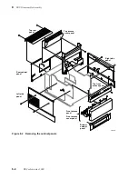
The printer features cabinet panels. To a certain degree the cabinet panels interlock; you
must remove some cabinet panels before you can remove others. You can remove the
following panels anytime:
n
Top rear panel (two screws).
n
Left and right side panels (two screws each.) Slide the front cover forward
and loosen the rear panel slightly before removing a side panel.
Before you remove the following panels, you must first remove the panels noted above:
n
Rear cabinet panel – remove the top rear panel first.
n
Top front cabinet panel – remove the front cover and open the top cover.
n
Bottom front cabinet panel – remove the front cover and the side panels.
n
Front cover panel – first remove the front cover.
n
Top cover panel (exit tray) – open the top cover and remove the two screws
securing it to the thermal head frame. Do not overtighten the screws during
reinstallation.
Tools required
n
#1 POSIDRIV® screwdriver
Summary of Contents for DECcolorwriter 1000
Page 11: ...Service Manual xi...
Page 16: ...Service Manual xv...
Page 56: ...2 24 DECcolorwriter 1000 2 Installing the Printer and Drivers...
Page 64: ...3 8 DECcolorwriter 1000 3 Verifying the Printer and Host Connections...
Page 70: ...4 6 DECcolorwriter 1000 4 Key Operator Training...
Page 170: ...8 46 DECcolorwriter 1000 8 FRU Disassembly Assembly...
Page 190: ...9 20 DECcolorwriter 1000 9 Checks and Adjustments...
Page 195: ...Service Manual A 5 Field Replaceable Units List A...
Page 198: ...A 8 DECcolorwriter 1000 A Field Replaceable Units List...
Page 204: ...C 6 DECcolorwriter 1000 C Wiring Diagrams...
Page 208: ...D 4 DECcolorwriter 1000 D Test Pattern Generator...

