Service Manual
8-15
FRU Disassembly/Assembly
8
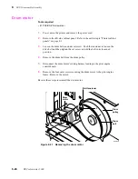
Removing the exit rollers
1.
Power down the printer and remove the power cord.
2.
Open the top cover and remove the front access cover. Also, remove the top
front, left and right side cabinet panels as described in “Printer cabinet
panels” on page 8-3.
3.
Lower exit roller: Remove the E-rings securing the lower exit roller pulley.
4.
Remove the lower exit roller pulley, roller, bushings and the paper-eject belt.
5.
Upper exit roller: Remove the E-rings securing the upper exit roller pulley.
Also remove the E-ring securing the other end of the roller.
6.
Remove the upper exit roller pulley, roller and bushings.
Reverse these steps to reinstall the exit rollers.
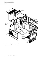
Figure 8-13 Removing the exit rollers
8345-31
Upper exit roller
Lower exit
roller
5
5
3
3
4
6
Summary of Contents for DECcolorwriter 1000
Page 11: ...Service Manual xi...
Page 16: ...Service Manual xv...
Page 56: ...2 24 DECcolorwriter 1000 2 Installing the Printer and Drivers...
Page 64: ...3 8 DECcolorwriter 1000 3 Verifying the Printer and Host Connections...
Page 70: ...4 6 DECcolorwriter 1000 4 Key Operator Training...
Page 170: ...8 46 DECcolorwriter 1000 8 FRU Disassembly Assembly...
Page 190: ...9 20 DECcolorwriter 1000 9 Checks and Adjustments...
Page 195: ...Service Manual A 5 Field Replaceable Units List A...
Page 198: ...A 8 DECcolorwriter 1000 A Field Replaceable Units List...
Page 204: ...C 6 DECcolorwriter 1000 C Wiring Diagrams...
Page 208: ...D 4 DECcolorwriter 1000 D Test Pattern Generator...

