Service Manual
8-29
FRU Disassembly/Assembly
8
Sensors and switches
The following topics explain how to remove sensors or switches that are difficult to
reach, require considerable print engine disassembly, or require special cautions.
Paper-pass sensor 1 and paper-empty sensor
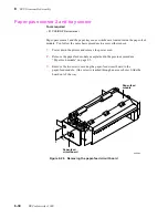
These sensors are located on the paper-feed module. The paper pass sensor 1 and the
paper empty sensor are soldered on the paper-feed circuit board. The board must be
replaced to replace the sensors. Refer to the earlier topic “Paper-feed module” on
page 8-5.
Thermal head position sensors
These sensors are mounted on a small circuit board that attaches to the top-side of the top
cover. It is easily accessible by removing the top cover panel.
Transfer roll mark sensors
The transfer roll mark sensor circuit board is mounted on the thermal head lift motor
bracket. To access and remove the sensor board, remove the thermal head lift motor as
explained in the previous procedure “Thermal head lift motor” on page 8-27. Upon
reassembly run the calibration procedure “Calibrating the transfer roll mark sensors
(reflective sensors)” on page 9-10 to ensure that they are in proper adjustment.
Summary of Contents for DECcolorwriter 1000
Page 11: ...Service Manual xi...
Page 16: ...Service Manual xv...
Page 56: ...2 24 DECcolorwriter 1000 2 Installing the Printer and Drivers...
Page 64: ...3 8 DECcolorwriter 1000 3 Verifying the Printer and Host Connections...
Page 70: ...4 6 DECcolorwriter 1000 4 Key Operator Training...
Page 170: ...8 46 DECcolorwriter 1000 8 FRU Disassembly Assembly...
Page 190: ...9 20 DECcolorwriter 1000 9 Checks and Adjustments...
Page 195: ...Service Manual A 5 Field Replaceable Units List A...
Page 198: ...A 8 DECcolorwriter 1000 A Field Replaceable Units List...
Page 204: ...C 6 DECcolorwriter 1000 C Wiring Diagrams...
Page 208: ...D 4 DECcolorwriter 1000 D Test Pattern Generator...


