Service Manual
8-37
FRU Disassembly/Assembly
8
Circuit boards
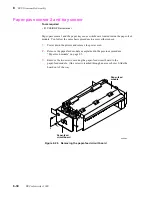
Power supply circuit board
Warning
Unplug the power cord to remove a possible electric shock hazard.
1.
Power down the printer. Unplug the power cord.
2.
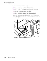
Remove the power supply as detailed in the previous procedure “Card cage
and power supply” on page 8-35.
3.
Disconnect the AC line voltage select switch's input connectors from the
power supply circuit board. Mark the lines so that you can reconnect them
properly; otherwise, you'll reverse the 115/220 AC settings.
4.
Disconnect the AC voltage wiring harness from CN2 (next to the fuses) of the
power supply circuit board.
5.
Disconnect the fan wiring harness from CN5 of the power supply circuit
board.
6.
Disconnect the ground cables leading from the power supply circuit board to
the card cage.
7.
Remove the two screws securing the power supply circuit board to the bottom
pan of the card cage.
8.
Squeeze the three snap-pins to release the power supply circuit board from the
bottom pan of the card cage.
9.
Slide the power supply circuit board away from the card cage to disconnect it
from the card cage interconnect board.
Tools required
n
#1 POSIDRIV® screwdriver
Summary of Contents for DECcolorwriter 1000
Page 11: ...Service Manual xi...
Page 16: ...Service Manual xv...
Page 56: ...2 24 DECcolorwriter 1000 2 Installing the Printer and Drivers...
Page 64: ...3 8 DECcolorwriter 1000 3 Verifying the Printer and Host Connections...
Page 70: ...4 6 DECcolorwriter 1000 4 Key Operator Training...
Page 170: ...8 46 DECcolorwriter 1000 8 FRU Disassembly Assembly...
Page 190: ...9 20 DECcolorwriter 1000 9 Checks and Adjustments...
Page 195: ...Service Manual A 5 Field Replaceable Units List A...
Page 198: ...A 8 DECcolorwriter 1000 A Field Replaceable Units List...
Page 204: ...C 6 DECcolorwriter 1000 C Wiring Diagrams...
Page 208: ...D 4 DECcolorwriter 1000 D Test Pattern Generator...

