Service Manual
8-41
FRU Disassembly/Assembly
8
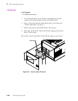
Card cage interconnect board
1.
Power down the printer. Leave the power cord plugged in to provide a
ground path for static discharges. Remove all interface cables.
2.
Remove the left side, right side and top-rear cabinet panels. Refer to the
earlier topic “Printer cabinet panels” on page 8-3.
3.
Remove the engine control board and the image processor board from the
card cage. Refer to the procedures “Engine control board” on page 8-39 and
“Image processor board” on page 8-43.
4.
Remove the card cage and power supply assembly as explained in the earlier
procedure “Card cage and power supply” on page 8-35.
5.
Remove the two screws securing the shield plate to the cardþcage.
6.
From underneath the card cage, remove the two screws securing the
interconnect board in place. Remove the board.
Reverse these steps to reinstall the interconnect circuit board.
Figure 8-36 Removing the interconnectþboard
8699-37
Summary of Contents for DECcolorwriter 1000
Page 11: ...Service Manual xi...
Page 16: ...Service Manual xv...
Page 56: ...2 24 DECcolorwriter 1000 2 Installing the Printer and Drivers...
Page 64: ...3 8 DECcolorwriter 1000 3 Verifying the Printer and Host Connections...
Page 70: ...4 6 DECcolorwriter 1000 4 Key Operator Training...
Page 170: ...8 46 DECcolorwriter 1000 8 FRU Disassembly Assembly...
Page 190: ...9 20 DECcolorwriter 1000 9 Checks and Adjustments...
Page 195: ...Service Manual A 5 Field Replaceable Units List A...
Page 198: ...A 8 DECcolorwriter 1000 A Field Replaceable Units List...
Page 204: ...C 6 DECcolorwriter 1000 C Wiring Diagrams...
Page 208: ...D 4 DECcolorwriter 1000 D Test Pattern Generator...


