Service Manual
9-7
Checks and Adjustments
9
9.
LED READY will turn off if the standard tray is selected.
10.
Set DIP Switch 1-3 off to exit the mode.
Reflective sensor auto-calibration
This procedure automatically calibrates the transfer roll mark sensors and the paper
clamped sensor. These sensors can also be individually calibrated in the later procedures
“Calibrating the transfer roll mark sensors (reflective sensors)” on page 9-10 and
“Calibrating the paper clamp sensor (reflective sensor)” on page 9-10. Place one or more
sheets of paper in the active tray and make sure that a 3-Color transfer roll is installed.
1.
Turn off the printer.
2.
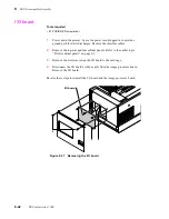
Remove the rear cabinet panel to access the engine control board. Refer to
the Chapter 8 topic “Printer cabinet panels” on page 8-3.
3.
Press and hold the TEST button and turn on the printer. Release the TEST
button. The printer is now in service mode.
4.
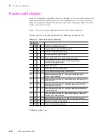
Set all the DIP 1 Switches off.
5.
Set DIP Switches 1-5, 1-6 and 1-7 on.
6.
Set DIP Switch 1-3 on to start the test. LEDs ERROR and JAM blink rapidly
to indicate the mode is active.
7.
Press the TEST button. The print engine advances the transfer roll to “read”
the transfer roll marks and calibrate the transfer roll mark sensors for the
contrast between the marks and the black stripe on the edge of the transfer
roll. LED READY blinks rapidly when the calibration completes.
8.
Press the TEST button again to make the printer pick a sheet of paper and
process it through the paper path. The test calibrates the paper clamped
sensor for the white level of the paper it passed through the print engine. If
the sensors all work properly, LED COVER blinks rapidly when the
calibration completes.
9.
Set DIP Switch 1-3 off to stop the test.
Summary of Contents for DECcolorwriter 1000
Page 11: ...Service Manual xi...
Page 16: ...Service Manual xv...
Page 56: ...2 24 DECcolorwriter 1000 2 Installing the Printer and Drivers...
Page 64: ...3 8 DECcolorwriter 1000 3 Verifying the Printer and Host Connections...
Page 70: ...4 6 DECcolorwriter 1000 4 Key Operator Training...
Page 170: ...8 46 DECcolorwriter 1000 8 FRU Disassembly Assembly...
Page 190: ...9 20 DECcolorwriter 1000 9 Checks and Adjustments...
Page 195: ...Service Manual A 5 Field Replaceable Units List A...
Page 198: ...A 8 DECcolorwriter 1000 A Field Replaceable Units List...
Page 204: ...C 6 DECcolorwriter 1000 C Wiring Diagrams...
Page 208: ...D 4 DECcolorwriter 1000 D Test Pattern Generator...


