9-12
DECcolorwriter 1000
9
Checks and Adjustments
Top margin adjustment
Note
Top margin refers to the top edge of test prints produced by the print
engine; the top edge of the test print is the edge inserted into the paper
clamp. Prints made via the image processor insert the bottom edge of
the print into the paper clamp.
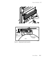
This adjustment sets how far a sheet of media is inserted into the paper clamp before it is
clamped. Consequently, it also set the print's top margin by forcing printing to begin at
the top of a page. The further the media is inserted into the paper clamp, the larger the
top margin will be. The margin specification (all four sides) is 5þmm,þ±3þmm.
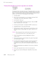
1.
Turn off the printer. Ensure that the paper tray is filled.
2.
Remove the rear cabinet panel to access the engine control board. Refer to
the Chapter 8 topic “Printer cabinet panels” on page 8-3.
3.
Press and hold the TEST button and turn on the printer. Release the TEST
button. The printer is now in service mode.
4.
Set DIP 1 Switches 1-3, 1-4,1-6 and 1-7 off.
5.
Set DIP Switches 1-5 on.
6.
Set DIP Switch 1-3 on to start the test. LEDs ERROR and JAM blink rapidly
to indicate the test is active. LEDs TRANSFER ROLL, COVER, and
READY blink to indicate the currently set top margin adjust value as
indicated in the chart below.
Table 9-4 Top margin adjust settings
TRANSFER
ROLL
COVER
READY
Top
margin
adjust
value
DIP
Switches
1-5
1-6
1-7
o
o
o
-3 mm
o
o
Z
-2 mm
↑
o
Z
o
-1 mm
↑
o
Z
Z
0
↑
↑
Z
o
o
1 mm
↑
Z
o
Z
2 mm
↑
↑
Z
Z
o
3 mm
↑
↑
Z
Z
Z
4 mm
↑
↑
↑
Summary of Contents for DECcolorwriter 1000
Page 11: ...Service Manual xi...
Page 16: ...Service Manual xv...
Page 56: ...2 24 DECcolorwriter 1000 2 Installing the Printer and Drivers...
Page 64: ...3 8 DECcolorwriter 1000 3 Verifying the Printer and Host Connections...
Page 70: ...4 6 DECcolorwriter 1000 4 Key Operator Training...
Page 170: ...8 46 DECcolorwriter 1000 8 FRU Disassembly Assembly...
Page 190: ...9 20 DECcolorwriter 1000 9 Checks and Adjustments...
Page 195: ...Service Manual A 5 Field Replaceable Units List A...
Page 198: ...A 8 DECcolorwriter 1000 A Field Replaceable Units List...
Page 204: ...C 6 DECcolorwriter 1000 C Wiring Diagrams...
Page 208: ...D 4 DECcolorwriter 1000 D Test Pattern Generator...


