9-14
DECcolorwriter 1000
9
Checks and Adjustments
Adjusting for best print quality
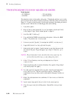
Thermal head temperature adjustment
This adjustments sets the reference pulse duration for the strobe pulses that drive each
thermal head element during printing. The longer the pulse duration is, the hotter the
element. During printing, the engine alters the pulse duration slightly to compensate for
ambient temperature, thermal head temperature, the color being printed, the history of
nearby printed dots and dot density. Properly adjusting the thermal head temperature is
the most significant adjustment you can make to maximize the printer's print quality.
1.
Power down the printer. Remove the upper rear panel to access the engine
control board.
2.
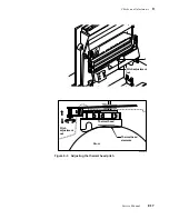
Refer to Table 9-4. Set DIP Switches 2-1 through 2-4 to the setting that
matches the resistance value printed on the thermal head.
This step sets a nominal value for the thermal head. You may change the
switch setting to achieve the best print quality.
3.
Print a dither pattern (test pattern 5). Refer to the earlier topic “Printing test
patterns” on page 9-2.
4.
With a properly adjusted thermal head you should see 14 steps or color shade
changes. (See Figure B-2.) If you don't see 14 steps, the thermal head
temperature is set too high and must be lowered. Set the thermal head to the
next available setting; use Table 9-4 to determine the setting.
5.
Repeat Steps 4 and 5 until you see 14 steps in the saturation dither pattern.
Magenta is the color you should judge color levels by. Do not try to achieve
14 steps with the color yellow. The human eye is somewhat insensitive to
shade changes to the color yellow. On rare occasions, it may be difficult to
achieve 14 levels of cyan or magenta. It may be necessary to compromise
those shades to 13 levels.
Summary of Contents for DECcolorwriter 1000
Page 11: ...Service Manual xi...
Page 16: ...Service Manual xv...
Page 56: ...2 24 DECcolorwriter 1000 2 Installing the Printer and Drivers...
Page 64: ...3 8 DECcolorwriter 1000 3 Verifying the Printer and Host Connections...
Page 70: ...4 6 DECcolorwriter 1000 4 Key Operator Training...
Page 170: ...8 46 DECcolorwriter 1000 8 FRU Disassembly Assembly...
Page 190: ...9 20 DECcolorwriter 1000 9 Checks and Adjustments...
Page 195: ...Service Manual A 5 Field Replaceable Units List A...
Page 198: ...A 8 DECcolorwriter 1000 A Field Replaceable Units List...
Page 204: ...C 6 DECcolorwriter 1000 C Wiring Diagrams...
Page 208: ...D 4 DECcolorwriter 1000 D Test Pattern Generator...

