9-16
DECcolorwriter 1000
9
Checks and Adjustments
Thermal head pitch (to correct speckle and wrinkle)
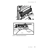
This adjustment corrects for speckles in the prints. This adjustment allows you to set the
pitch or tilt of the thermal head's elements in relation to the drum surface as illustrated in
Figure 9-3. Properly setting the pitch of the thermal head places the printing elements in
optimum contact with the drum, eliminating speckles and wrinkling.
1.
Turn off the printer.
2.
Remove the top rear cabinet panel to access the engine control board. Refer
to the Chapter 8 topic “Printer cabinet panels” on page 8-3.
3.
Set all the DIP 1 Switches off.
4.
Press and hold the TEST button and turn on the printer. Release the TEST
button. The printer is now in service mode.
5.
Select test pattern 0 “Speckle,” by ensuring that all DIP 1 switches are off.
6.
Toggle DIP Switch 1-8 on then off to start the print.
7.
Examine the print for speckle. Speckles appear as pale blue dropouts in the
blue field of the print. If speckle appears, go to Step 10. Otherwise, go to
Step 8.
Caution
The pitch adjustment rotates about four turns from stop to stop. Do
not force the nut past the stops; you may damage the printer.
8.
With a 7/32-inch nutdriver, turn the pitch adjustment nut 1/2þturn
counterclockwise.
9.
Print out another speckle test print and examine it for speckles. Repeat Step 8
and 9 until speckles first appear.
10.
Now that speckle are apparent in the test prints, rotate the pitch adjustment
nut 1/2 turn clockwise. Print out a speckle test pattern. Continue this
adjustment until you reach the point in which speckles disappear from the test
prints.
11.
Rotate the pitch adjustment nut an additional 1/2 turn clockwise to finish the
adjustment.
12.
Apply cement compound to the nut to lock it in its current position.
13.
Close the top cover and turn off the printer. Reinstall the rear top cabinet
panel.
Tools required
n
#1 POSIDRIV
®
n
7/32-inch nutdriver
n
screwdriver
n
cement compound
Summary of Contents for DECcolorwriter 1000
Page 11: ...Service Manual xi...
Page 16: ...Service Manual xv...
Page 56: ...2 24 DECcolorwriter 1000 2 Installing the Printer and Drivers...
Page 64: ...3 8 DECcolorwriter 1000 3 Verifying the Printer and Host Connections...
Page 70: ...4 6 DECcolorwriter 1000 4 Key Operator Training...
Page 170: ...8 46 DECcolorwriter 1000 8 FRU Disassembly Assembly...
Page 190: ...9 20 DECcolorwriter 1000 9 Checks and Adjustments...
Page 195: ...Service Manual A 5 Field Replaceable Units List A...
Page 198: ...A 8 DECcolorwriter 1000 A Field Replaceable Units List...
Page 204: ...C 6 DECcolorwriter 1000 C Wiring Diagrams...
Page 208: ...D 4 DECcolorwriter 1000 D Test Pattern Generator...


